
Home > WHITE RODGERS > WHITE-RODGERS 1F86-0471 Blue Single 1 1 Stage Thermostat Instruction Manual
WHITE-RODGERS 1F86-0471 Blue Single 1 1 Stage Thermostat Instruction Manual


INSTALLATION
Batteries
WARNING
!
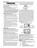
2 "AA" alkaline batteries are included in the thermostat. To in-
stall the batteries, pull the battery door as shown by the arrow
and lift open. Using the polarity indicated inside the battery
door, insert the batteries. To close the battery door, swing the
door down while pulling in the direction of arrow. Once fully
down, snap the door back into position.
Thermostat installation and all components of the
control system shall conform to Class II circuits per
the NEC code.
Remove Old Thermostat
To replace the batteries, set system to OFF, following the
instructions above.
A standard heat/cool thermostat consists of three basic parts:
1. The cover, which may be either a snap-on or hinge type.
2. The base, which is removed by loosening all captive
screws.
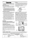
Figure 1 – Battery door shown open
3. The switching subbase, which is removed by unscrewing
the mounting screws that hold it on the wall or adapter
plate. Before removing wires from old thermostat, label
each wire with the terminal designation from which it
was attached. Disconnect the wires from the old thermo-
stat one at a time. Do not let wires fall back into the wall.
“AA” Alkaline Batteries
Installing New Thermostat
1. Pull the thermostat body off the thermostat base. Forcing
or prying on the thermostat will cause damage to the unit.
2. Place base over hole in wall and mark mounting hole
locations on wall using base as a template.
Thermostat can be powered by system AC power or Battery.
If
is displayed, the thermostat is battery powered. If
is not displayed, thermostat is system powered with
optional battery back-up. When battery power remain-
ing is approximately half, the will be displayed. When
"Change " is displayed, install fresh “AA” alkaline batter-
ies immediately. For best results, replace all batteries with a
premium brand alkaline battery such as Duracell® or Ener-
gizer®. We recommend replacing batteries every 2 years. If
the home is going to be unoccupied for an extended period
3. Move base out of the way. Drill mounting holes. If you
are using existing mounting holes and the holes drilled
are too large and do not allow you to tighten base snug-
ly, use plastic screw anchors to secure the base.
4. Fasten base snugly to wall using mounting holes shown
in Figure 2 and two mounting screws. Leveling is for
appearance only and will not affect thermostat operation.
5. Connect wires to terminal block on base.
6. Push excess wire into wall and plug hole with a fire re-
sistant material (such as fiberglass insulation) to prevent
drafts from affecting thermostat operation.
7. Carefully line the thermostat up with the base and snap
into place.
(over 3 months) and
is displayed, the batteries should
be replaced before leaving. When less than two months of
battery life remain, the setpoint temperature will offset by
10 degrees (10 degrees cooler in Heat mode / 10 degrees
warmer in Cool mode). If offset occurs, the normal setpoint
can be manually reset with
or
. Another offset will
occur within two days if batteries are not replaced.
SS/HP Switch
Figure 2 – Thermostat base and rear view of thermostat
(Conventional or Heat Pump Selection)
The SS/HP switch is factory set to the SS position. In this posi-
tion, thermostat is configured as conventional single stage. If
you have a single stage heat pump system, switch SS/HP to
HP position (see figure 2).
Mounting
Hole
Mounting
Hole
Place Level
across
Mounting Tabs
(for appearance only)
Place Level
across
Mounting Tabs
(for appearance only)
Gas/Elec Switch (Fan Option)
The GAS/ELEC switch is factory set to the GAS position. In
this position, the thermostat will not power the circulator fan on
a call for heat, but will power the circulator on a call for cool.
If your system requires that the thermostat power the circula-
tor fan on a call for heat, this switch should be set to the ELEC
position. Typically, gas and oil heating systems do not require
the thermostat to power the circulator fan during a call for heat.
If your heat is gas or oil, the switch should be set to the GAS
position.
When the thermostat is configured for Heat Pump, the thermo-
stat will always power the circulator fan on a call for heat in the
HEAT mode.
GAS
ELEC
SS/HP
Switch
SS
HP
GAS/ELEC Switch
WIRING CONNECTIONS
Refer to equipment manufacturers' instructions for specific system wiring information. After wiring, see CONFIGURATION
section for proper thermostat configuration. Refer to 37-6754 for 1F80-0471 wiring diagram specifications.
TERMINAL DESIGNATION DESCRIPTIONS
Terminal Designation Description
Terminal Designation Description
O/B ........................ (SS) Power closed for 3 wire zone
HP) Changeover valve for heat pump
Y............................ Compressor Relay
W........................... Heat Relay
RH ........................ Power for Heating
RC ........................ Power for Cooling
C.......................... Common wire from secondary side of
cooling system transformer or heat
only system transformer
G............................ Fan Relay
2

| General | Details |
|---|---|
| Name | WHITE-RODGERS 1F86-0471 Blue Single 1 1 Stage Thermostat Instruction Manual |
| Make | WHITE RODGERS |
| Language | English |
| Filetype | PDF (Download) |
| File size | 0.51 MB |
 (1 votes, average: 5.00 out of 5)
 Loading...

White-Rodgers 1E78 Non Programmable Heat Only Thermostat User Manual

White-Rodgers 1F97-1277 Big Blue Single Stage Thermostat User Manual

White-Rodgers 1F56N-444 Thermostat User Manual

White-Rodgers 1F83-277 Heating & Air Conditioning Auto Changeover Heat Pump Thermostat User Manual

White-Rodgers M30 Thermostat Instruction Manual

WHITE-RODGERS 1F51N-619 Low Voltage Evaporative Cooler Thermostat Instruction Manual

White Rodgers 1F78-151 Non Programmable Thermostat Instructions

WHITE RODGERS 1F80-51 Programmable Electronic Digital Thermostat Instruction Manual

WHITE-RODGERS 1F90-71 5-Day 2-Day Electronic Digital Thermostat Instruction Manual

WHITE-RODGERS 1F95-1277 Universal Thermostat Owner’s Manual


TechPunt E1 Smart WiFi Radiator Thermostat User Guide

Danfoss RET1001M – V2 Room Thermostat Installation Guide

sygonix 2735095 Wireless Heating Thermostat Instruction Manual

GREYSTONE TLFLF24X01 Flying Lead Low Limit Thermostat Instruction Manual

SECURE ThermoPlus AS2 Programmable Room Thermostat Instruction Manual

Haswill Electronics STC-9100 Thermostat User Manual

Lachin TDS72 Series WiFi Thermostat User Guide

emos P5606OT Programmable Electronic Indoor Thermostat User Manual

SIEMENS TH192 HC Heating-Cooling Room Thermostat Instruction Manual

EBECO EB-Therm 500 Floor Heating Thermostat Instruction Manual