
Home > WHITE RODGERS > White-Rodgers 1E78 Non Programmable Heat Only Thermostat User Manual
White-Rodgers 1E78 Non Programmable Heat Only Thermostat User Manual


CONTENTS
Preparations ................................................ 1
Thermostat Details ...................................... 1
Removing Old Thermostat........................... 1
Mounting and Wiring.................................... 2
Check Thermostat Operation....................... 3
Specifications .............................................. 4
Troubleshooting ........................................... 4
Installation Instructions for
Heating & Air Conditioning
1E78
Non-Programmable Heat Only Thermostat
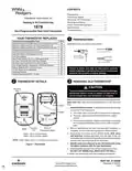
YOUR THERMOSTAT REPLACES
Typical System Compatibility Chart
PREPARATIONS
1
Assemble tools required as shown below.
1E78
Standard Heat Only Two Wire Gas or Oil Fired Systems (24 volt)
Electronic Ignition Heat Only Two Wire Systems (24 volt)
Electronic Ignition Heat Only Gas or Oil Fired Systems (24 volt)
Standard Heat/Cool Systems (24 volt)
Yes
Yes
Yes
No
No
No
No
No
Yes
No
No
Yes
Yes
No
No
FLAT BLADE SCREWDRIVER
Heat/Cool Systems Electric Heat (24 volt)
Heat Only Electric Heat Systems (24 volt)
Cool Only Systems
HAND OR POWER
DRILL WITH 3/16 INCH
DRILL BIT, IF NEEDED
Heat Pump Systems (No Aux. or Emergency Heat)
Hot Water Zone Heat Only (Two Wire) Systems
Hot Water Zone Heat Only (Three Wire) Systems
Line Voltage Heating or Baseboard 110/240 Volt Systems
Millivolt Systems Floor or Wall Furnaces
12 VDC Mobile Home Application
WIRE CUTTER/STRIPPER
Failure to follow and read all instructions carefully
beforeinstallingoroperatingthiscontrolcouldcause
personal injury and/or property damage.
Multistage Systems
Systems Exceeding 30VAC, 1.5 Amp
THERMOSTAT DETAILS
REMOVING OLD THERMOSTAT
2
3
CAUTION
Topreventelectricalshockand/orequipmentdamage,
disconnect electric power to system at main fuse or
circuit breaker box until installation is complete.
!
Mounting
Hole
Before removing wires from old thermostat’s switching subbase,
label each wire with the terminal designation it was removed
from.
W904
W905
RC
Y
G
O
RH
B
W
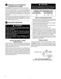
1. Remove OldThermostat: A standard heat/cool thermostat
consists of three basic parts:
a. The cover, which may be either a snap-on or hinge type.
b. The base, which is removed by loosening all captive
screws.
c. The switching subbase, which is removed by unscrewing
the mounting screws that hold it on the wall or adaptor
plate.
Back of
Thermostat Body
Mounting
Hole
2. Shut off electricity at the main fuse box until installation is
complete. Ensure that electrical power is disconnected.
Base
3. Remove the front cover of the old thermostat. With wires
still attached, remove wall plate from the wall. If the old
thermostathasawallmountingplate,removethethermostat
and the wall mounting plate as an assembly.
W904 - clip for Celcius display
W905 - clip for hydronic system
NOTE: Earlier models refer to 37-7006 for jumper locations.
4. Identify each wire attached to the old thermostat using
the labels enclosed with the new thermostat.
Figure 1.Thermostat
5. Disconnectthewiresfromtheoldthermostatoneatatime.
DO NOT LET WIRES FALL BACK INTO THE WALL.
6. Install new thermostat using the following procedures.
PART NO. 37-6620B
Replaces 37-6620A
1026


| General | Details |
|---|---|
| Name | White-Rodgers 1E78 Non Programmable Heat Only Thermostat User Manual |
| Make | WHITE RODGERS |
| Language | English |
| Filetype | PDF (Download) |
| File size | 0.27 MB |
 (1 votes, average: 5.00 out of 5)
 Loading...

White-Rodgers 1F97-1277 Big Blue Single Stage Thermostat User Manual

White-Rodgers 1F56N-444 Thermostat User Manual

White-Rodgers 1F83-277 Heating & Air Conditioning Auto Changeover Heat Pump Thermostat User Manual

White-Rodgers M30 Thermostat Instruction Manual

WHITE-RODGERS 1F51N-619 Low Voltage Evaporative Cooler Thermostat Instruction Manual

WHITE-RODGERS 1F90-71 5-Day 2-Day Electronic Digital Thermostat Instruction Manual

WHITE-RODGERS 1F95-1277 Universal Thermostat Owner’s Manual

White Rodgers 1F78-151 Non Programmable Thermostat Instructions

WHITE RODGERS 1F80-51 Programmable Electronic Digital Thermostat Instruction Manual

WHITE-RODGERS 1F86-0471 Blue Single 1 1 Stage Thermostat Instruction Manual

White-Rodgers 1E78 Only Manual: Questions and Answers
Can White-Rodgers 1E78 Only work with heat pump systems or cool only systems?
No. This thermostat is designed for heat only systems. It does not support heat pump systems, cool only systems, or any heat/cool combination. User Manual, p. 1
What does the battery symbol mean on White-Rodgers 1E78 Only display?
The battery icon indicates the alkaline batteries are low and need replacement with fresh AAA Energizer batteries. User Manual, p. 2
How do I attach the thermostat base to the wall?
Position the base over the wall hole, mark mounting locations, drill holes, and fasten loosely with two screws. Adjust until level, then tighten.
- Remove packing material and pull thermostat body straight off the base.
- Connect wires beneath terminal screws on base using the appropriate wiring schematic.
- Place base over hole in wall and mark mounting hole locations using base as a template.
- Move base out of the way and drill the marked holes.
- Fasten base loosely to wall with two mounting screws.
- Adjust base until level, then tighten screws completely. For oversized holes, use plastic screw anchors. User Manual, p. 2
Other White-Rodgers 1E78 manuals
More White-Rodgers thermostat manuals

TX1000 Thermostat Instruction Manual

GENERAL LIFE MITRA 220 Digital Room Thermostat User Manual

Homematic IP BMOAONSUT Radiator Thermostat User Manual

Orbegozo FDR 65 Litres Adjustable Thermostat Instruction Manual
Nexans N-Comfort Kt+ Thermostat Instruction Manual

AIRZONE IBPRO6 FLEXA 3.0 Blueface Zero Wired Thermostat User Manual

STELPRO SAT402ZB Smart Thermostat User Guide

Honeywell Home TH8320R1003-Uv VisionPRO 8000 with RedLINK Multistage Thermostat Installation Guide

MOES BRT-100 Radiator Thermostat User Guide

DIMPLEX ML2TA 2KW Convector Heater With Thermostat Instruction Manual