Home > WHITE RODGERS > White Rodgers 1F78-151 Non Programmable Thermostat Instructions
White Rodgers 1F78-151 Non Programmable Thermostat Instructions
CONTENTS
Preparations .................................................. 1
Thermostat Details ........................................ 1
Removing Old Thermostat............................. 1
Mounting and Wiring...................................... 2
Check Thermostat Operation......................... 3
Specifications ................................................ 5
Troubleshooting ............................................. 5
Installation Instructions for
Heating & Air Conditioning
1F78
Non-Programmable Thermostat
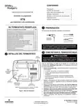
YOUR THERMOSTAT REPLACES
Typical System Compatibility Chart
PREPARATIONS
1
Assemble tools required below.
1F78
Standard Heat Only Two Wire Gas or Oil Fired Systems (24 volt)
Electronic Ignition Heat Only Two Wire Systems (24 volt)
Electronic Ignition Heat Only Gas or Oil Fired Systems (24 volt)
Standard Heat/Cool Systems (24 volt)
Ye s
Ye s
Ye s
Ye s
Ye s
Ye s
Ye s
Ye s
Ye s
No
FLAT BLADE SCREWDRIVER
Heat/Cool Systems Electric Heat (24 volt)
Heat Only Electric Heat Systems (24 volt)
Cool Only Systems (24 volt)
HAND OR POWER
DRILL WITH 3/16 INCH
DRILL BIT, IF NEEDED
Heat Pump Systems (No Aux or Emergency Heat)
Hot Water Zone Heat Only (Two Wire) Systems
Hot Water Zone Heat Only (Three Wire) Systems
Line Voltage Heating or Baseboard 110/240 Volt Systems
Millivolt Systems Floor or Wall Furnaces
WIRE CUTTER/STRIPPER
No
Failure to follow and read all instructions carefully
before installing or operating this control could cause
personal injury and/or property damage
Ye s
Ye s
No
12 VDC Mobile Home Application
Multistage Systems
Systems Exceding 30VAC, 1.5 Amp
No
REMOVING OLD THERMOSTAT
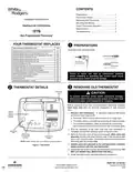
THERMOSTAT DETAILS
3
2
Mounting
hole
CAUTION
!
To prevent electrical shock and/or equipment damage,
disconnect electrical power to the system at the main fuse
or circuit breaker until installation is complete.
-
-
+
+
Before removing wires from old thermostat’s switching subbase,
label each wire with the terminal designation it was removed
from.
W
RH
B
RC
W904
Clip for
Celsius
Display
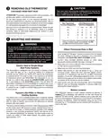
1. Remove Old Thermostat: A standard heat/cool thermostat
consists of three basic parts:
W904
G
O
Y
a. The cover, which may be either a snap-on or hinge type.
b. The base, which is removed by loosening all captive screws.
W905
c. The switching subbase, which is removed by unscrewing
the mounting screws that hold it on the wall or adaptor plate.
ELEC GAS
2. Shut off electricity at the main fuse box until installation is
complete. Ensure that electrical power is disconnected.
Mounting
hole
W905 Clip
for Hydronic
System
3. Remove the front cover of the old thermostat. With wires still
attached, remove wall plate from the wall. If the old thermostat
has a wall mounting plate, remove the thermostat and the wall
mounting plate as an assembly.
Electric/Gas
Switch
NOTE: Earlier models refer to 37-7006 for jumper locations.
4. Identify each wire attached to the old thermostat using the
labels enclosed with the new thermostat.
Figure 1.Thermostat
5. Disconnect the wires from the old thermostat one at a time. DO
NOT LET WIRES FALL BACK INTO THE WALL.
6. Install new thermostat using the following procedures.
PART NO. 37-6615C
Replaces 37-6615B
1028
| General | Details |
|---|---|
| Name | White Rodgers 1F78-151 Non Programmable Thermostat Instructions |
| Make | WHITE RODGERS |
| Language | English |
| Filetype | PDF (Download) |
| File size | 0.42 MB |

White-Rodgers 1E78 Non Programmable Heat Only Thermostat User Manual

White-Rodgers 1F97-1277 Big Blue Single Stage Thermostat User Manual

White-Rodgers 1F56N-444 Thermostat User Manual

White-Rodgers 1F83-277 Heating & Air Conditioning Auto Changeover Heat Pump Thermostat User Manual

White-Rodgers M30 Thermostat Instruction Manual

WHITE-RODGERS 1F51N-619 Low Voltage Evaporative Cooler Thermostat Instruction Manual

WHITE RODGERS 1F80-51 Programmable Electronic Digital Thermostat Instruction Manual

WHITE-RODGERS 1F86-0471 Blue Single 1 1 Stage Thermostat Instruction Manual

WHITE-RODGERS 1F90-71 5-Day 2-Day Electronic Digital Thermostat Instruction Manual

WHITE-RODGERS 1F95-1277 Universal Thermostat Owner’s Manual

White Rodgers 1F78-151 Non Programmable Thermostat Instructions Overview
Summary of Contents
- Page 1: Preparations Assemble tools required below. Failure to follow and read all instructions carefully before installing or operating this control could cause personal injury and/or property damage. Removing Old Thermostat To prevent electrical shock and/or equipment damage, disconnect electrical power to the system at the main fuse or circuit breaker until installation is complete. Before removing wires from old thermostat’s switching subbase, label each wire with the terminal designation it was removed from. A standard heat/cool thermostat consists of three basic parts: the cover, the base, and the switching subbase. Shut off electricity at the main fuse box until installation is complete. Ensure that electrical power is disconnected. Identify each wire attached to the old thermostat using the labels enclosed with the new thermostat. Disconnect the wires from the old thermostat one at a time. Do not let wires fall back into the wall. Install new thermostat using the following procedures.
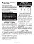
- Page 2: Caution: Take care when securing and routing wires to avoid shorting to adjacent terminals or the rear of the thermostat. Removing old thermostat: This product does not contain mercury, but may replace a unit that does. Terminal cross reference chart: New thermostat terminal designations compared to other manufacturers. Warning: Do not use on circuits exceeding specified voltage to avoid damage and hazards. Attach thermostat base to wall: Remove packing material and gently pull the cover straight off the base. Electric heat or single-stage heat pump systems: The thermostat is configured to operate a heat/cool, fossil fuel forced air system. Battery location: This thermostat requires 2 “AAA” alkaline batteries to operate. Hydronic heating systems: The thermostat must be set to operate properly with hot water or steam systems. Factory default setting: The thermostat is set for forced air heat, with options for longer heating cycles for hydronic systems. Replace batteries annually for best results.
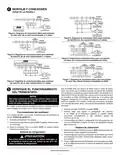
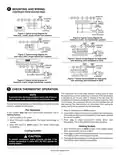
- Page 3: Mounting and wiring Typical wiring diagram for heat only, 3-wire, single transformer systems Typical wiring diagram for heat/cool, 5-wire, two-transformer systems Reversing valve is energized when the system switch is in the COOL position Typical wiring diagram for cool only, 3-wire, single transformer systems Typical wiring diagram for heat pump with reversing valve energized in COOL Red jumper wire must be connected between thermostat RH and RC terminals for proper thermostat operation This thermostat has a time delay between cooling cycles to allow the head pressure in the compressor to stabilize To prevent static discharge problems, touch side of thermostat to release static build-up before touching any keys To prevent compressor and/or property damage, if the outdoor temperature is below 50°F, do not operate the cooling system.
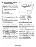
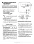
- Page 4: Check thermostat operation Before you begin using your thermostat, you should be familiar with its features and with the display and the location and operation of the thermostat buttons. Your thermostat consists of two parts: the thermostat cover and the base. To remove the cover, gently pull it straight out from the base. To replace the cover, line up the cover with the base and press gently until the cover snaps onto the base. The thermostat buttons and switches include an up arrow to raise the temperature setting and a down arrow to lower it. The fan switch has options for ON and AUTO, while the system switch has settings for COOL, OFF, and HEAT. The display shows the current temperature and the currently set temperature, which is blank when the system switch is in the OFF position. You can enter both your heating and cooling setpoints at the same time. Your new thermostat has been accurately set in the factory, but you may adjust the temperature display to match your old thermostat. The factory default setting is Fahrenheit, but it can be altered to Celsius by clipping a jumper on the circuit board.
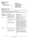
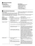
- Page 5: SPECIFICATIONS Electrical rating: 0 to 30 VAC 50/60 Hz or D.C. Setpoint temperature range: 45°F to 90°F (7°C to 32°C) Operating ambient temperature range: 32°F to 105°F (0°C to 41°C) Operating humidity range: 0 to 90% RH (non-condensing) Shipping temperature range: -40°F to 150°F (-40°C to 66°C) TROUBLESHOOTING If a voltage spike or static discharge causes erratic thermostat operation, you can reset the thermostat. For best results, replace batteries once a year with new premium brand alkaline batteries. Common problems include blown fuse or tripped circuit breaker. Verify thermostat and system wires are securely attached. If the thermostat does not click after being reset, contact your heating and cooling service person.
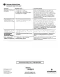
- Page 6: Troubleshooting Heat, cool or fan runs constantly. Possible causes include a short in wiring, thermostat, or heat/cool/fan system. Check wire connections and reset the thermostat. If the issue persists, consult the manufacturer or service person. Furnace cycles too fast or too slow. Digital thermostats may cycle faster than older models. To increase cycle time, clip Jumper W-905. If issues continue, contact a local service person. Cooling cycles too fast or too slow. The cycle rate for cooling is fixed and cannot be adjusted. Consult a local service person for suggestions. Thermostat setting and thermometer disagree. Adjust the thermostat thermometer setting by +/- 3 degrees as needed. Blank display and/or keypad not responding. Possible causes include a voltage spike or the need for a battery change. Replace batteries and check the heat/cool system for proper operation.
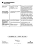
- Page 7: Solución de problemas El modo de calor, frío o ventilador funciona de manera constante. Verifique todas las conexiones de los cables para asegurarse de que no estén en cortocircuito o tocándose entre sí. Los ciclos de la caldera son demasiado cortos o demasiado largos. Normalmente, los termostatos digitales proporcionan un control preciso de la temperatura. Si desea aumentar la duración del ciclo, corte el cable de puente W-905. Los ciclos de refrigeración son demasiado cortos o demasiado largos. La duración del ciclo de refrigeración es fija y no se puede ajustar. El ajuste del termostato y el termómetro del termostato no coinciden. El termómetro puede ajustarse en +/- 3 grados. La pantalla está en blanco y/o el teclado no responde.
- Page 8: Especificaciones Datos eléctricos Características eléctricas: 0 a 30 VCA 50/60 hz. o D.C. Rango de temperaturas de referencia: 45°F a 90°F (7°C a 32°C) Temperatura ambiente operativa: 32°F a 105°F (0ºC a 41ºC) Humedad operativa: 0 a 90% HR (sin condensación) Temperatura de transporte: -40°F a 150°F (-40ºC a 66ºC) Solución de problemas Si un pico de voltaje o una descarga estática pone en blanco la pantalla, puede reajustar el termostato. Para obtener resultados óptimos, cambie las pilas una vez al año por pilas alcalinas nuevas. El sistema no calienta/enfría: verifique el fusible, el interruptor de alimentación y las conexiones. Condición de bloqueo de la caldera puede causar calefacción intermitente. Si el termostato no hace un chasquido después de reajustarlo, póngase en contacto con el servicio técnico.
- Page 9: Verifique el funcionamiento del termostato. Antes de usar su termostato, familiarícese con sus funciones y la pantalla. El termostato consta de dos partes: la cubierta y la base. Para retirar la cubierta, tire suavemente de ella. Los botones e interruptores del termostato incluyen ajustes de temperatura y modos de funcionamiento. La pantalla muestra la temperatura actual y la temperatura programada. El termostato viene ajustado de fábrica, pero se puede ajustar la pantalla de temperatura. Puede ingresar temperaturas de calefacción y refrigeración al mismo tiempo. La luz de fondo mejora el contraste de la pantalla en condiciones de poca luz. El ajuste predeterminado de fábrica es en grados Fahrenheit, pero se puede cambiar a grados Celsius.
- Page 10: Montaje y conexiones Sistema de termostato Diagrama de conexiones típico para sistemas de solo calor de un solo transformador y 3 cables Diagrama de conexiones típico para sistemas de calor/frío de dos transformadores y 5 cables Nota: Para solo calor con 2 cables, conectar a RH y W Diagrama de conexiones típico para sistemas de solo frío de un solo transformador y 3 cables Nota: El cable de puente rojo debe conectarse entre las terminales RH y RC del termostato Este termostato tiene una demora de tiempo entre los ciclos de refrigeración Verifique el funcionamiento del termostato Para evitar problemas de descarga estática, toque la parte lateral del termostato ¡Precaución! Para evitar daños al compresor, no utilice el sistema de refrigeración si la temperatura externa está por debajo de los 50°F
- Page 11: ¡PRECAUCIÓN! Al fijar y pasar los cables, tenga cuidado de que no hagan cortocircuito con las terminales adyacentes o en la parte trasera del termostato. Podrían producirse lesiones personales y/o daños materiales. Este producto no contiene mercurio. No obstante, puede reemplazar una unidad que sí contiene mercurio. No abra las celdas de mercurio. En el caso de que una celda se dañe, no toque el mercurio derramado. El mercurio no debe desecharse con los residuos domésticos. Para desechar la unidad que será reemplazada por este equipo, colóquela en un recipiente adecuado. No utilizar en circuitos que excedan el voltaje especificado. Un voltaje superior dañará el control y podría causar riesgos de choques eléctricos o incendio. La instalación del termostato y de todos los componentes del sistema debe cumplir con las reglamentaciones del código NEC para circuitos de clase II. Este termostato está configurado de fábrica para operar un sistema de aire forzado con combustible fósil (gas, aceite, etc.) de calor/frío. Este termostato requiere 2 pilas alcalinas “AAA” para funcionar. Si aparece el mensaje significa que las pilas tienen poca carga y deben cambiarse. La configuración predeterminada de fábrica es de calor por aire forzado. Si se corta el cable de puente W905 en el tablero del circuito se producirá un ciclo de calefacción más largo que lo normal para sistemas de agua caliente o vapor. Ambas configuraciones producen un control de temperatura sumamente exacto y pueden ajustarse según su preferencia personal.
- Page 12: Preparación Procúrese las herramientas indicadas a continuación. Detalles del termostato ¡Precaución! Desconecte la alimentación eléctrica al sistema en el disyuntor o caja de fusibles principal hasta que la instalación esté terminada. Cómo retirar el termostato viejo Retire el termostato viejo: un termostato de calor/frío consta de tres partes básicas. Apague la electricidad en la caja de fusibles principal hasta que haya finalizado la instalación. Identifique cada uno de los cables conectados al termostato viejo usando las etiquetas incluidas con el nuevo termostato. Desconecte los cables del termostato viejo de a uno a la vez. No deje que los cables vuelvan a introducirse en la pared. Instale el termostato nuevo siguiendo el procedimiento indicado.