Home > WHITE RODGERS > White-Rodgers 1F83-277 Heating & Air Conditioning Auto Changeover Heat Pump Thermostat User Manual

White-Rodgers 1F83-277 Heating & Air Conditioning Auto Changeover Heat Pump Thermostat User Manual
1F83-277  
Heating & Air Conditioning  
Non-programmable, Auto Changeover, Multi-Stage/Heat  
Pump Thermostat  
INSTALLATION INSTRUCTIONS  
Operator: Save these instructions for future use!  
FAILURE TO READ AND FOLLOW ALL INSTRUCTIONS CAREFULLY BE-  
FORE INSTALLING OR OPERATING THIS CONTROL COULD CAUSE PER-  
SONAL INJURY AND/OR PROPERTY DAMAGE.  
PREPARATIONS  
YOUR THERMOSTAT REPLACES  
Assemble tools required as shown below.  
Description  
1F83-277  
Yes  
Heat Pump (No Aux. or Emergency Heat)  
Heat Pump (with Aux. or Emergency Heat)  
Standard Heat & Cooling Systems  
Two Stage Heat & Two Stage Cool  
Standard Heat Only Systems  
Yes  
Yes  
Yes  
FLAT BLADE SCREWDRIVER  
WIRE CUTTER/STRIPPER  
Yes  
HAND OR POWER  
DRILL WITH 3/16 INCH  
DRILL BIT, IF NEEDED  
Millivolt Heat Only Systems – Floor or Wall Furnaces  
Standard Central Air Conditioning  
Gas or Oil Heat  
Yes  
Yes  
Yes  
Electric Furnace  
Yes  
Hydronic (Hot Water) Zone Heat – 2 Wires  
Hydronic (Hot Water) Zone Heat – 3 Wires  
Yes  
No  
REMOVING OLD THERMOSTAT  
CAUTION  
!
To prevent electrical shock and/or equipment damage,  
disconnect electric power to system at main fuse or  
circuit breaker box until installation is complete.  
Before removing wires from old thermostat's switching sub-  
base, label each wire with the terminal designation it was  
removed from.  
Y2  
C
R
E/W1  
Y1  
1. Shut off electricity at the main fuse box until installation is  
complete. Ensure that electrical power is disconnected.  
O
B
L
W2  
G
Mounting  
Hole  
Mounting  
Hole  
ELEC.  
GAS  
2. Remove Old Thermostat: A standard heat/cool  
thermostat consists of three basic parts:  
a. The cover, which may be either a snap-on or  
hinge type.  
Elec-Gas  
Switch  
ON  
AUTO  
b. The base, which is removed by loosening all  
captive screws.  
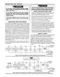
Figure 1 – Thermostat base  
c. The switching subbase, which is removed by  
unscrewing the mounting screws that hold it on  
the wall or adaptor plate.  
ATTENTION! This product does not contain mercury. How-  
ever, this product may replace a unit which contains mercury.  
3. Remove the front cover of the old thermostat. With  
wires still attached, remove wall plate from the wall. If  
the old thermostat has a wall mounting plate, remove the  
thermostat and the wall mounting plate as an assembly.  
Do not open mercury cells. If a cell becomes damaged, do not  
touch any spilled mercury. Wearing non-absorbent gloves,  
clean up the spilled mercury and place into a container which  
can be sealed. If a cell becomes damaged, the unit should be  
discarded.  
4. Identify each wire attached to the old thermostat.  
5. Disconnect the wires from the old thermostat one at a  
time. DO NOT LET WIRES FALL BACK INTO THE  
WALL.  
Mercury must not be discarded in household trash. When the  
unit this product is replacing is to be discarded, place in a  
location to send product containing mercury.  
6. Install new thermostat using the following procedures.  
PART NO. 37-6509E  
Replaces 37-6509D  
0818  
White-Rodgers is a division  
of Emerson Electric Co.  
GeneralDetails
NameWhite-Rodgers 1F83-277 Heating & Air Conditioning Auto Changeover Heat Pump Thermostat User Manual
MakeWHITE RODGERS
LanguageEnglish
FiletypePDF (Download)
File size0.24 MB
Download PDF
1 Star2 Stars3 Stars4 Stars5 Stars (1 votes, average: 5.00 out of 5)
Loading...
White-Rodgers 1E78 Non Programmable Heat Only Thermostat User Manual
White-Rodgers 1F97-1277 Big Blue Single Stage Thermostat User Manual
White-Rodgers 1F56N-444 Thermostat User Manual
White-Rodgers M30 Thermostat Instruction Manual
WHITE-RODGERS 1F51N-619 Low Voltage Evaporative Cooler Thermostat Instruction Manual
WHITE-RODGERS 1F95-1277 Universal Thermostat Owner’s Manual
White Rodgers 1F78-151 Non Programmable Thermostat Instructions
WHITE RODGERS 1F80-51 Programmable Electronic Digital Thermostat Instruction Manual
WHITE-RODGERS 1F86-0471 Blue Single 1 1 Stage Thermostat Instruction Manual
WHITE-RODGERS 1F90-71 5-Day 2-Day Electronic Digital Thermostat Instruction Manual

White-Rodgers 1F83-277 Heating & Air Conditioning Auto Changeover Heat Pump Thermostat User Manual
Get the free PDF manual for the White-Rodgers 1F83-277 Heating & Air Conditioning Auto Changeover Heat Pump Thermostat User Manual and access setup steps, usage instructions, and troubleshooting tips. 👉 View online or download now to keep your thermostat running smoothly!
White-Rodgers 1F83-277 Heating & Air Conditioning Auto Changeover Heat Pump Thermostat User Manual Overview
Summary of Contents

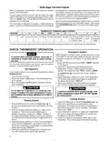
  • Page 1: Heating & air conditioning non-programmable, auto changeover, multi-stage/heat pump thermostat installation instructions. Failure to read and follow all instructions carefully before installing or operating this control could cause personal injury and/or property damage. Assemble tools required for installation. Disconnect electric power to the system at the main fuse or circuit breaker box until installation is complete. Label each wire with the terminal designation it was removed from before removing wires from the old thermostat's switching sub-base. Remove the old thermostat by loosening all captive screws and unscrewing the mounting screws that hold it on the wall. This product does not contain mercury, but may replace a unit which does. Disconnect the wires from the old thermostat one at a time, ensuring they do not fall back into the wall. Mercury must not be discarded in household trash; refer to the appropriate disposal guidelines for products containing mercury. Install the new thermostat using the specified procedures.
  • Page 2: Mounting and wiring Take care when securing and routing wires so they do not short to adjacent terminals or rear of thermostat. Do not use on circuits exceeding specified voltage. Remove the packing material from the thermostat. Gently pull the cover straight off the base. Connect wires beneath terminal screws on base using appropriate wiring schematic. Thermostat installation and all components of the system shall conform to Class II circuits per the NEC code. Fasten base loosely to wall using two mounting screws. Leveling is for appearance only. This thermostat is configured from the factory to operate a heat/cool, fossil fuel forced air system. 2 “AA” alkaline batteries are included in the thermostat at the factory with a battery tag to prevent power drainage. If “BATT” is displayed, the batteries are low and should be replaced. All wiring diagrams are for typical systems only. Refer to equipment manufacturers’ instructions for specific system wiring information.
  • Page 3: Wiring diagrams must observe polarity to avoid equipment damage. The accessory relay scheme is required when safety circuits exist in both systems. Two commons must be jumpered together in the wiring setup. Refer to equipment manufacturers' instructions for specific wiring information. This thermostat is designed to operate a single-transformer system. You can configure the thermostat for various heat pump system types. The 24 volt neutral connection to terminal C on the thermostat is not required if batteries are replaced annually. Typical wiring diagrams illustrate configurations for two transformer heat pump systems and single transformer multi-stage systems. Ensure proper thermostat configuration after wiring. Limit or safety switches are critical components in the system wiring.
  • Page 4: Multi-stage terminal outputs require specific wiring information from equipment manufacturers. For a two-transformer system, remove the transformer from the system without safety circuits and jumper the two commons together. The thermostat can be configured for either multi-stage electric heat or multi-stage gas systems. In electric heat configuration, the G terminal will be energized on a call for heat. Refer to the terminal output information for proper wiring of the thermostat. The thermostat is designed for a single-transformer system; cut and tape off terminals for a two-transformer system. Emergency mode bypasses the heat pump to use the heat source wired to terminal E. To prevent static discharge, touch the side of the thermostat before pressing any keys. If the system does not operate properly during testing, contact a qualified service person. Do not operate the cooling system if the outdoor temperature is below 50°F.
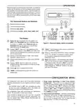
  • Page 5: Operation Before programming your thermostat, familiarize yourself with its features and the display. Your thermostat consists of two parts: the thermostat cover and the base. To remove the cover, pull it straight out from the base. To replace the cover, line up the cover with the base and press until it snaps onto the base. The display shows various icons indicating the system's mode, such as HEAT and COOL. FAULT will be displayed when there is a malfunction in the system. The display indicates when the batteries are low with BATT. The configuration menu allows you to set certain thermostat operating characteristics. You can configure the thermostat for single stage, multi-stage, or heat pump operation. The factory default setting for cycle selection is fast cycle.
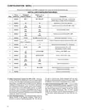
  • Page 6: Configuration menu instructions are provided for setting up the system. Press the SYSTEM button until OFF is displayed to access the installer/configuration menu. Select single stage, multi-stage, or heat pump system configuration. Choose fast or slow cycle selection for the system. Compressor lockout can be set to OFF or ON to protect the compressor from short cycling. Backlight display can be selected to improve visibility in low lighting conditions. Fast second stage can be enabled or disabled based on temperature adjustments. Filter replacement run time can be selected in increments of 50. Temperature display can be adjusted to Fahrenheit or Celsius. Keypad lockout options are available to secure the system settings.
  • Page 7: Select filter replacement run time – The thermostat will display FLTR after a set time of operation. This is a reminder to change or clean your air filter. Keypad Lockout – This menu selection will display a lock icon and “OFF” (default, keypad not locked out). Select Temperature Display Adjustment 4 LO to 4 HI – Allows you to adjust the room temperature display up to 4° higher or lower. Select F° or C° Readout – Changes the display readout to Centigrade or Fahrenheit as required. Selected Auto mode – This control will feature AUTO changeover mode when AU on is selected (default). Limited Heat Range – This feature provides a maximum setpoint temperature for heat. The default setting is 90°F. Limited Cool Range – This feature provides a minimum setpoint temperature for cool. The default setting is 45°F. Electrical Rating: 20 to 30 VAC 50/60 Hz or DC. Setpoint Temperature Range: 45°F to 90°F (7°C to 32°C). Operating Ambient Temperature Range: 32°F to 105°F.
  • Page 8: Operation The system mode is selected by pressing the SYSTEM button. Icons on the bottom right corner of the display will indicate the mode: COOL, AUTO, HEAT, EMER, or OFF. In AUTO mode, the heat setpoint temperature cannot be the same as or higher than the cool setpoint temperature. When the thermostat is in AUTO mode, both the flame and snowflake icons are displayed. If the room temperature raises above the HEAT setpoint and a call for cool is required, the temperature displayed will change to the COOL setpoint. Low battery indicator will display LO BATT when the batteries are low and should be replaced. You cannot program with low batteries, but you can override setpoint temperature. After LO BATT has been displayed for 4 weeks, the thermostat will adjust temperatures automatically. Your thermostat is designed to determine the optimum time to activate the second stage. If a voltage spike or static discharge causes erratic thermostat operation, you can reset the thermostat.
  • Page 9: Troubleshooting Heating system requires service or thermostat requires replacement. Diagnostic: Press SYSTEM button to HEAT and raise the setpoint above room temperature. If the thermostat does not click, try the reset operation. If the thermostat clicks, contact the furnace manufacturer or a service person. Cooling system requires service or thermostat requires replacement. Check each wire connection to verify they are not shorted or touching together. Digital thermostats normally provide precise temperature control and may cycle faster than older mechanical models. The location of the thermostat and/or the size of the heating system may be influencing the cycle rate. Thermostat thermometer setting requires adjustment. Blank display and/or keypad not responding.
  • Page 10: Troubleshooting Possible cause Corrective action Symptom Forgot keypad Lockout code This resets the thermostat to factory default settings of the configuration menu. Your thermostat is designed to determine the optimum time to activate the second stage. There is a time delay from 0-30 minutes depending on the performance of the first stage of the system. Your thermostat display can be set to display temperature in Fahrenheit or Celsius. My display light does not work. Can it be fixed or replaced? When the thermostat compressor time delay occurs it will flash the setpoint for about five minutes. My setpoint temperature is flashing. What does that mean?
  • Page 11: Page 11
  • Page 12: Page 12