
Home > WHITE RODGERS > White-Rodgers 1F83-277 Heating & Air Conditioning Auto Changeover Heat Pump Thermostat User Manual
White-Rodgers 1F83-277 Heating & Air Conditioning Auto Changeover Heat Pump Thermostat User Manual
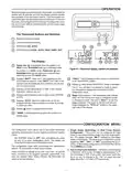



Multi-Stage Terminal Outputs
Refer to equipment manufacturers' instructions for specific one transformer. If transformer safety circuits are in only one of
system wiring information.
the systems, remove the transformer of the system with NO
safety circuits. If required, replace remaining transformer with a
75VAClassIItransformer. Afterdisconnectingonetransformer,
the two commons must be jumpered together.
You can configure the thermostat for use with either multi-stage
electric heat systems or multi-stage gas systems. When config-
ured for electric heat, the G terminal (blower/fan) will be
energized on a call for heat.
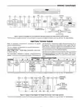
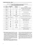
Use the terminal output information below to help you wire the
thermostat properly for your multi-stage system. After wiring,
see CONFIGURATION section for proper thermostat configu-
ration.
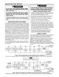
This thermostat is designed to operate a single-transformer
system. If you have a two-transformer system, cut and tape off
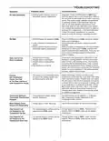
THERMOSTAT TERMINALS (MULTI-STAGE)
W2 E/W1 Y2 Y1
Multi-stage Malfunction 24 Volt 24 Volt Heat Mode Heat mode Cool Mode Cool Mode Blower/Fan Energized Energized Energized
SYSTEM
L
C*
R
G
O
B
Light
(Common) (Hot) 2nd stage 1st stage 2nd stage 1st stage on call for Cool (and
in Cool in Heat, Off,
Heat if configured
to Electric Heat)
Mode
Emergency
Modes
*The 24 volt neutral connection to terminal C on the thermostat is not required if you replace the batteries once a year with fresh “AA” alkaline batteries.
CHECK THERMOSTAT OPERATION
Emergency System
NOTE
EMER bypasses the Heat Pump to use the heat source wired
to terminal E on the thermostat. EMER is typically used when
compressor operation is not desired, or you prefer back-up
heat only.
To prevent static discharge problems, touch side of
thermostat to release static build-up before touching
any keys.
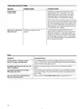
1. Press SYSTEM button to select EMER. “EMER” will flash
on the display.
If at any time during testing your system does not operate
properly, contact a qualified service person.
2. Press
to adjust thermostat setting above room
temperature. The Aux. heating system will begin to
Fan Operation
operate. The display will show “STG1” flashing “EMER”
If your system does not have a G terminal connection, skip to
Heating System.
and Flame icon ( ) to indicate that the Aux. system is
operating.
1. Turn on power to system.
2. Move FAN switch to ON position. The blower should be-
gin to operate.
3. Adjust temperature setting to 3° above room temperature.
The auxiliary heat system should begin to operate and
the display should show “STG1+2”.
3. Move FAN switch to AUTO position. The blower should
stop immediately.
4. Press to adjust the thermostat below room tempera-
ture. The Aux. heating system should stop operating.
CAUTION
!
CAUTION
To prevent compressor and/or property damage, if the
outdoor temperature is below 50°F, DO NOT operate
the cooling system.
!
Do not allow the compressor to run unless the com-
pressor oil heaters have been operational for 6 hours
and the system has not been operational for at least 5
minutes.
Cooling System
Heating System
1. Press SYSTEM button to select the Snowflake icon ( ).
2. Press
1. Press SYSTEM button to select the Flame icon ( ). If
the auxiliary heating system has a standing pilot, be sure
to light it.
to adjust thermostat setting below room
temperature. The blower should come on immediately on
high speed, followed by cold air circulation. The display
should show “STG1”.
2. Press
to adjust thermostat setting to 1° above room
3. Adjust temperature setting to 3° below room temperature.
The second stage cooling should begin to operate and
the display should show “STG1+2”.
temperature. The heating system should begin to
operate. The display should show “STG1”. However, if
the setpoint temperature display is flashing, the compres-
sor lockout feature is operating (see Configuration menu,
item 5).
4. Press
to adjust the temperature setting above room
temperature. The cooling system should stop operating.
3. Adjust temperature setting to 3° above room temperature.
If your system configuration is set at MS2, HP2 or HP1,
the auxiliary heat system should begin to operate and the
display should show “STG1+2”.
4. Press
to adjust the thermostat below room tempera-
ture. The heating system should stop operating.
4

| General | Details |
|---|---|
| Name | White-Rodgers 1F83-277 Heating & Air Conditioning Auto Changeover Heat Pump Thermostat User Manual |
| Make | WHITE RODGERS |
| Language | English |
| Filetype | PDF (Download) |
| File size | 0.24 MB |
 (1 votes, average: 5.00 out of 5)
 Loading...

White-Rodgers 1E78 Non Programmable Heat Only Thermostat User Manual

White-Rodgers 1F97-1277 Big Blue Single Stage Thermostat User Manual

White-Rodgers 1F56N-444 Thermostat User Manual

White-Rodgers M30 Thermostat Instruction Manual

WHITE-RODGERS 1F51N-619 Low Voltage Evaporative Cooler Thermostat Instruction Manual

WHITE-RODGERS 1F86-0471 Blue Single 1 1 Stage Thermostat Instruction Manual

WHITE-RODGERS 1F90-71 5-Day 2-Day Electronic Digital Thermostat Instruction Manual

WHITE-RODGERS 1F95-1277 Universal Thermostat Owner’s Manual

White Rodgers 1F78-151 Non Programmable Thermostat Instructions

WHITE RODGERS 1F80-51 Programmable Electronic Digital Thermostat Instruction Manual


ENGO CONTROLS E25-BATW Zig Bee 868MHz Smart Thermostat User Guide

Honeywell DT4R Wireless Modulating Room Thermostat Instruction Manual

GENERAL LIFE FH100S Underfloor Heating Thermostat User Manual

STELPRO ST302P Programmable Electronic Thermostat Owner’s Manual

HTS HY02TP Programmable Plug In Thermostat User Manual

Danfoss RAV Ally Radiator Thermostat User Guide

BVF Heating L-1 Smart Outdoor Thermostat User Manual

UNIWATT UT202NP Series Non Programmable Electronic Thermostat Owner’s Manual

Tio 230v Thermostat User Manual

COMBUSTION CONTROL Anti Siphon Device Flue Gas Safety Thermostat Instruction Manual