Home > WHITE RODGERS > WHITE-RODGERS 1F90-71 5-Day 2-Day Electronic Digital Thermostat Instruction Manual

WHITE-RODGERS 1F90-71 5-Day 2-Day Electronic Digital Thermostat Instruction Manual
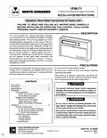
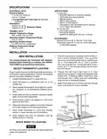
1F90-71  
5-Day/2-Day Electronic Digital Thermostat  
WHITE-RODGERS  
INSTALLATION INSTRUCTIONS  
Operator: Save these insructions for future use!  
FAILURE TO READ AND FOLLOW ALL INSTRUCTIONS CAREFULLY  
BEFORE INSTALLING OR OPERATING THIS CONTROL COULD CAUSE  
PERSONAL INJURY AND/OR PROPERTY DAMAGE.  
DESCRIPTION  
This wall-mounted, low voltage thermostat maintains  
room temperature by controlling the operation of heating  
and cooling systems. The user may program up to four  
time/temperature settings per 24 hour period. The ther-  
mostat stores independent heating and cooling programs  
for 5-day (weekday) and 2-day (weekend) periods. The  
thermostat will store both heating and cooling programs  
simultaneously.ThreeAAEnergizer® batterieswillmain-  
tain the stored program for approximately one year, if  
incoming power should fail. If power failure is extensive  
and the program is lost, after power restoration, the  
thermostat will automatically maintain a factory  
preprogrammed heating temperature of 64°F or a cooling  
temperature of 82°F.  
PRECAUTIONS  
Ifindoubtaboutwhetheryourwiringismillivolt,line,orlow Do not exceed the specification ratings.  
voltage, have it inspected by a qualified heating and air  
All wiring must conform to local and national electrical  
codes and ordinances.  
conditioning contractor, electrician, or someone familiar  
with basic electricity and wiring.  
This control is a precision instrument, and should be  
handled carefully. Rough handling or distorting compo-  
nents could cause the control to malfunction.  
CONTENTS  
CAUTION  
!
Description ......................................................... 1  
Precautions ........................................................ 1  
Specifications..................................................... 2  
Installation.......................................................... 2  
New Installation  
To prevent electrical shock and/or equipment  
damage, disconnect electric power to system, at  
main fuse or circuit breaker box, until installation  
is complete.  
Select Thermostat Location  
Route Wires to Location  
Replacement Installation  
WARNING  
!
Remove Old Thermostat  
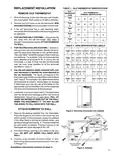
Attach Subbase to Wall  
Attach Thermostat to Subbase  
Operation ........................................................... 6  
System Configuration  
Do not use on circuits exceeding specified volt-  
age. Higher voltage will damage the control and  
could cause shock or fire hazard.  
A. Set Group A Option Switches  
B. Set Group B Option Switches  
C. Electric Heat Systems  
Donotshortoutterminalsongasvalveorprimary  
control to test. Short or incorrect wiring will burn  
out thermostat and could cause personal injury  
and/or property damage.  
Check Thermostat Operation  
Fan Operation  
Heating System  
Cooling System  
Troubleshooting  
WHITE-RODGERS DIVISION  
EMERSON ELECTRIC CO.  
9797 REAVIS ROAD  
PART NO. 37-5086B  
Replaces 37-5086A  
9517  
Printed in U.S.A.  
ST. LOUIS, MISSOURI 63123-5398  
R
GeneralDetails
NameWHITE-RODGERS 1F90-71 5-Day 2-Day Electronic Digital Thermostat Instruction Manual
MakeWHITE RODGERS
LanguageEnglish
FiletypePDF (Download)
File size0.13 MB
Download PDF
1 Star2 Stars3 Stars4 Stars5 Stars (1 votes, average: 5.00 out of 5)
Loading...
White-Rodgers 1E78 Non Programmable Heat Only Thermostat User Manual
White-Rodgers 1F97-1277 Big Blue Single Stage Thermostat User Manual
White-Rodgers 1F56N-444 Thermostat User Manual
White-Rodgers 1F83-277 Heating & Air Conditioning Auto Changeover Heat Pump Thermostat User Manual
White-Rodgers M30 Thermostat Instruction Manual
WHITE-RODGERS 1F51N-619 Low Voltage Evaporative Cooler Thermostat Instruction Manual
White Rodgers 1F78-151 Non Programmable Thermostat Instructions
WHITE RODGERS 1F80-51 Programmable Electronic Digital Thermostat Instruction Manual
WHITE-RODGERS 1F86-0471 Blue Single 1 1 Stage Thermostat Instruction Manual
WHITE-RODGERS 1F95-1277 Universal Thermostat Owner’s Manual

WHITE-RODGERS 1F90-71 5-Day 2-Day Electronic Digital Thermostat Instruction Manual
Get the free PDF manual for the WHITE-RODGERS 1F90-71 5-Day 2-Day Electronic Digital Thermostat Instruction Manual and access setup steps, usage instructions, and troubleshooting tips. 👉 View online or download now to keep your thermostat running smoothly!
WHITE-RODGERS 1F90-71 5-Day 2-Day Electronic Digital Thermostat Instruction Manual Overview
Summary of Contents

  • Page 1: 5-Day/2-Day Electronic Digital Thermostat Installation instructions Operator: Save these instructions for future use. Failure to read and follow all instructions carefully could cause personal injury and/or property damage. This wall-mounted, low voltage thermostat maintains room temperature by controlling the operation of heating and cooling systems. The user may program up to four time/temperature settings per 24 hour period. The thermostat will store both heating and cooling programs simultaneously. If in doubt about whether your wiring is millivolt, line, or low voltage, have it inspected by a qualified heating and air conditioning contractor. All wiring must conform to local and national electrical codes and ordinances. To prevent electrical shock and/or equipment damage, disconnect electric power to system until installation is complete. Do not use on circuits exceeding specified voltage.
  • Page 2: Specifications Electrical rating: 17 to 30 VAC, 50/60 Hz. Maximum total load: 1.5 Amps (all terminals combined). Applications include standard heat/cool or heat-only systems, three-wire zone valve systems, millivolt systems, electric heat systems, and gas or oil fired systems. Do not use with multi-stage systems or heat pump systems. Setpoint temperature range: 40°F to 99°F (4°C to 37°C). Operating ambient temperature range: 32°F to 105°F. Operating humidity range: 0 to 90% RH (non-condensing). Select thermostat location: locate about 5 ft. above the floor on a partitioning wall. Avoid locations close to windows, outside walls, or doors leading outside. All wiring must conform with local and national electrical codes and ordinances.
  • Page 3: Old thermostat identification is crucial for replacement installation. Shut off electricity at the main fuse box until installation is complete. Remove the front cover of the old thermostat while keeping wires attached. Disconnect the two wires from the old thermostat for heating-only systems. Identify the terminals that have wires attached on the old thermostat for heating/cooling systems. Use self-adhesive labels to identify the wires attached to the old thermostat. Label each wire as you disconnect it to avoid confusion during installation. Pull at least six inches of wire out of the wall when disconnecting. Remove the packing material from the thermostat before installation. Connect wires beneath terminal screws on the sub-base using the appropriate wiring schematic.
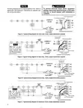
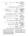
  • Page 4: Caution: All wiring diagrams are for typical systems only. Refer to equipment manufacturers’ instructions for specific system wiring information. To prevent electrical shock and/or equipment damage, disconnect electrical power at the main fuse box or circuit breaker until installation is complete. Red jumper wire (provided with thermostat) must be connected between thermostat's RH and RC terminals for proper thermostat operation with this system. Typical wiring diagram for heat only, 2-wire, single transformer systems. Typical wiring diagram for heat only, 3-wire, single transformer systems. Typical wiring diagram for cool only, 3-wire, single transformer systems. Typical wiring diagram for heat/cool, 4-wire, single transformer systems.
  • Page 5: From millivolt system Thermostat terminal connections Typical wiring diagram for millivolt systems From 24 VAC transformer Cooling system Fan Hot relay From zone valve Typical wiring diagram for heat only, 3-wire, zone valve systems Place subbase over hole in wall and mark mounting hole locations on wall using subbase as a template. Push excess wire into wall and plug hole with a fire-resistant material to prevent drafts from affecting thermostat operation.
  • Page 6: Attach thermostat to subbase. Be gentle when attaching the thermostat to avoid damage. Ensure connector pins and plastic snaps are properly aligned. Set option switches to desired position before attaching to subbase. Program the thermostat with batteries installed before attaching. Turn thermostat off before attaching to wall to prevent equipment damage. Engage two lower guides and pivot up to attach the thermostat. Do not remove the AA batteries when changing Group A option switches. Remove batteries for a minimum of two minutes when changing Group B option switches. Limited temperature range allows temperature adjustment within programmed limits.
  • Page 7: Manual changeover for heating/cooling systems involves specific steps for fan operation. For heat only systems, ensure the jumper wire is properly installed between the RH and RC terminals. Cool only systems require pressing the fan switch until FAN AUTO is displayed. Computed energy management recovery (EMR) enables the system to reach programmed temperature before the next program period begins. To activate the heating system, adjust the thermostat above room temperature. Electric heat systems may have a lockout bypass option for qualified service technicians only. The thermostat has a built-in short term time delay to protect the compressor. Group B option switches must be set correctly for automatic changeover. Testing thermostat operation can be done by pressing specific buttons at startup. Do not use the lockout bypass option unless certain conditions regarding the compressor have been met.
  • Page 8: After the system has been checked and is running properly, determine if automatic changeover is desired. Refer to the operation guide if you need additional information on thermostat operation. To prevent compressor and/or property damage, if power to the compressor has been off or interrupted for more than 1 hour and the outdoor temperature is below 50°F, do not operate the system for at least the amount of time the compressor was off. Refer to the Question & Answer section of the operation guide for information on troubleshooting the thermostat. Press to adjust thermostat below room temperature to call for cool. The blower should come on immediately, followed by cold air circulation. If the blower does not come on and the word COOL is flashing, the compressor lockout feature is operating. If the thermostat display is operating properly, but the cooling system does not operate, the red jumper wire may not be properly installed between the RH and RC terminals. Disconnect electrical power to the system and properly install the jumper wire per the appropriate wiring diagram.