
Home > WHITE RODGERS > White-Rodgers 1F56N-444 Thermostat User Manual
White-Rodgers 1F56N-444 Thermostat User Manual


REMOVING OLD THERMOSTAT (cont’d)
3
If no heat anticipator/indication is showing, do not be concerned; move on to the
next step.
ATTENTION! This product does not contain mercury. However, this product may
Installation Instructions for:
1F56N-444
replace a unit which contains mercury.
Horizontal
Snap-Action
Do not open mercury cells. If a cell becomes damaged, do not touch any spilled
mercury. Wearing non-absorbent gloves, take up the spilled mercury and place into
a container which can be sealed. If a cell becomes damaged, the unit should be
discarded.
Vertical
Snap-Action
1E56N-444
Mercury must not be discarded in household trash. When the unit this product is
ers.com for location to send product containing mercury.
YOUR THERMOSTAT REPLACES
System
Models
MOUNTING AND WIRING
Standard Heating & Cooling Systems –
4 or 5 wires
4
Standard Heat Only Systems
Standard Central Air Conditioning
Gas or Oil Heat
Hydronic (Hot Water) Zone Heat – 2 wires
Electric Furnace
WARNING
!
All Models
Do not use on circuits exceeding specified voltage. Higher voltage will
damage control and could cause shock or fire hazard.
Do not short out terminals on gas valve or primary control to test. Short or
incorrect wiring will damage thermostat and could cause personal injury
and/or property damage.
Heat Pump (No Aux or Emergency Heat)
Heat Pump (with Aux or Emergency Heat)
Baseboard Electric Heating or Line Voltage
(120 or 240 Volt)
None
Thermostat installation and all components of the system shall conform to
Class II circuits per the NEC code.
Millivolt Heat Only Systems –
Floor or Wall Furnaces
Hydronic (Hot Water) Zone Heat – 3 wires
All Models
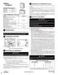
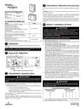
A. Remove base from subbase: Loosen the screws on the base and remove.
B. Mount switching subbase: Use the screws provided to mount the subbase or
wallplate to wall (see Fig. 1).
PREPARATIONS
1
Assemble tools required: power drill, flat blade screwdriver, wire cutter/stripper, level.
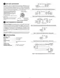
C. Attach wires to appropriate terminals:
• For two wire systems (Heat Only or Cool Only). Replace subbase with wall-
plate. If you have a two-wire Heat Only system, attach one wire to R and one to
wire W. If you have a two-wire Cool Only system, attach one wire to R and one to
wire to Y. Tighten any unused terminals securely. (see Fig. 5 and 6).
Failure to follow and read all instructions carefully before installing or operat-
ing this control could cause personal injury and/or property damage.
•
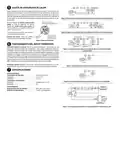
If your system has more than two wires: Use the cross reference chart to
determine correct wire connections. If you have a four-wire heat/cool system leave
the factory installed jumper between RC and RH attached (see Fig 2.). If your sys-
tem has five wires remove the factory installed jumper between RC and RH (see
Fig 3.).
THERMOSTAT FEATURES
2
FAN
SYSTEM
AUTO
ON
COOL OFF HEAT
•
Electric heat or single stage heat pump systems: These thermostats are
configured from the factory to operate a heat/cool, fossil fuel (gas, oil, etc.) forced
air system. This is correct for any system that DOES NOT require the thermostat
to energize the fan on a call for heat. If your system is an electric heat or heat-
pump system that REQUIRES the thermostat to turn on the fan on a call for heat,
remove the yellow factory-installed jumper wire from the Y terminal and connect
it to the A terminal. This will allow the thermostat to energize the fan immediately
on a call for heat. If you are unsure if the heating system requires the thermostat
to control the fan, contact a qualified heating and air conditioning service person.
For single stage heat pump applications (no auxillary heat), install a short jumper
wire (not included) across terminals W and Y. If the system has a reversing valve
connection energized in Cooling, attach it to O. If the system has a reversing valve
connection energized in Heating, attach it to B (see Fig. 4).This thermostat will not
provide multi-stage heating or cooling.
G
RC
4
B
O
W
R
5
Y
6
RH
A
Y
Mounting Screw
Mounting Screw
KEEP THIS AREA
CLEAR OF WIRES
Hole
in Wall
Mounting Hole
Mounting Hole
Figure 1. Thermostat subbase and wallplate
REMOVING OLD THERMOSTAT
D. Mount Thermostat Base: Gently push excess wire back into the wall opening
and plug hole with a fire-resistant material, such as fiberglass insulation to prevent
drafts from affecting thermostat operation. Mount the thermostat base to the sub-
base using the three captive screws on the thermostat base. (See Fig. 1) Tighten
the screws securely. Proceed to Step #5.
3
CAUTION
!
To prevent electrical shock and/or equipment damage, disconnect electrical pow-
er to the system at the main fuse or circuit breaker until installation is complete.
CAUTION
!
Before removing wires from old thermostat’s switching subbase, label each wire with
the terminal designation it was removed from.
Take care when securing and routing wires so they do not short to adjacent
terminals or rear of thermostat. Personal injury and/or property damage may
occur.
1. Remove OldThermostat: A standard heat/cool thermostat consists of three basic
parts:
a. The cover, which may be either a snap-on or hinge type.
b. The base, which is removed by loosening all captive screws.
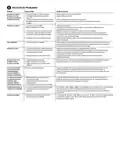
TERMINAL CROSS REFERENCE CHART
New Thermostat
Other Manufacturers’
c. The switching subbase, which is removed by unscrewing the mounting
screws that hold it on the wall or adaptor plate.
Terminal Designation
Terminal Designation
*
*
RH
RC
G
4
R
G
W
Y
RH
R
M
V
F
R5
–
R
Make a note here
of the anticipator setting on the old thermostat for
–
G
W
Y
future reference and use in step 5.
G
G
The heat anticipator pointer, if adjustable, will be set at one of a series of numbers
representing the current rating of the primary control in your furnace. The number will
be one of the following: .2, .4, .8, etc. or 0.2, 0.4, 0.8, etc.
W
W
Y
H
C
4
Y
Y6
* These are four-wire, single-transformer systems. Factory installed jumper wire
between the RH and RC terminals must remain in place.
PART NO. 37-6881B
Replaces 37-6881A
0921


| General | Details |
|---|---|
| Name | White-Rodgers 1F56N-444 Thermostat User Manual |
| Make | WHITE RODGERS |
| Language | English |
| Filetype | PDF (Download) |
| File size | 0.42 MB |
 (1 votes, average: 5.00 out of 5)
 Loading...

White-Rodgers 1E78 Non Programmable Heat Only Thermostat User Manual

White-Rodgers 1F97-1277 Big Blue Single Stage Thermostat User Manual

White-Rodgers 1F83-277 Heating & Air Conditioning Auto Changeover Heat Pump Thermostat User Manual

White-Rodgers M30 Thermostat Instruction Manual

WHITE-RODGERS 1F51N-619 Low Voltage Evaporative Cooler Thermostat Instruction Manual

White Rodgers 1F78-151 Non Programmable Thermostat Instructions

WHITE RODGERS 1F80-51 Programmable Electronic Digital Thermostat Instruction Manual

WHITE-RODGERS 1F86-0471 Blue Single 1 1 Stage Thermostat Instruction Manual

WHITE-RODGERS 1F90-71 5-Day 2-Day Electronic Digital Thermostat Instruction Manual

WHITE-RODGERS 1F95-1277 Universal Thermostat Owner’s Manual

White-Rodgers 1F56N-444 Manual: Questions and Answers
How do I install the White-Rodgers 1F56N-444 thermostat on my wall?
Mount the switching subbase to the wall using provided screws, attach wires to terminals, then secure the thermostat base to the subbase with three captive screws.
- Loosen the screws on the base and remove it from the subbase.
- Use provided screws to mount the subbase or wallplate to the wall.
- Attach wires to appropriate terminals based on your system type.
- Gently push excess wire into the wall opening and plug with fire-resistant material like fiberglass insulation.
- Mount the thermostat base to the subbase using the three captive screws.
- Tighten all screws securely. User Manual, p. 1
What wires connect to R, W, Y, G, O and B terminals on White-Rodgers 1F56N-444?
Terminal connections depend on your system type. Consult the cross reference chart and wiring diagrams for your specific configuration.
| Terminal | Use |
|---|---|
| RH | Heating transformer power |
| RC | Cooling transformer power |
| G | Fan |
| W | Heat |
| Y | Cool |
| O | Reversing valve (cooling energized) |
Can I use the White-Rodgers 1F56N-444 with a heat pump that has auxiliary or emergency heat?
Yes, the thermostat is designed to work with heat pump systems that include auxiliary or emergency heat. User Manual, p. 1
Do I need to remove the factory jumper wire between RC and RH when installing this thermostat?
Remove the jumper if your system has five wires. Leave it attached if you have a four-wire heat/cool system. User Manual, p. 1
More White-Rodgers thermostat manuals

MYSON Unisenza Digital Thermostat User Manual

EpheyFIF WITH3 Wireless Gas Boiler Thermostat User Guide

SIEMENS M3182 Room Thermostat Instruction Manual

Honeywell RLV4305 Programmable Thermostat Owner’s Manual

somfy 1870776 Wired IO Thermostat Instructions

STELPRO STZW402+ Electronic Thermostat for The Smart Home Owner’s Manual

SALUS HTRS-RF Wireless Digital Thermostat Instruction Manual

PNI-CT40 Smart Wireless Thermostat User Manual

Honeywell TH8732WFH5004 Round Smart Thermostat User Guide

T10 Pro Smart Thermostat with Redlink Room Sensor