Puravent CFST Frost Thermostat Installation Guide


Installation Instructions
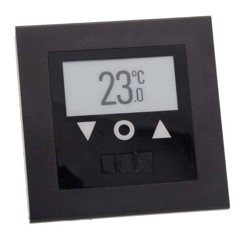
CFST Frost Thermostat
Note
Electrical Installation should be carried out by a suitably qualified person to the latest edition of
the IEE Requirements for Electrical Installations.(BS7671:2001)
Isolate the power supply before beginning installation
LOCATION.
The thermostat should be located on an internal wall at an height of about 1.5m so as to allow
an unobstructed airflow around it. Avoid locations where the thermostat may be influenced by
doors, windows, direct sunlight, the heater or any other heat source. The objective is to sense
ambient air temperature.
FIXING
Remove control knob by turning to maximum setting and carefully levering off with small
screwdriver. Remove front cover by loosening single screw.
Securely fix base via mounting holes either to a standard BS4662 wall box or directly to a
suitable surface.
HEAT ANTICIPATOR
Connection of the heat anticipator resistor will give a more accurate and stable control.
CONNECTION
Wire the Live supply to terminal 1 and the Live feed to the heater to terminal 3.
Wire a neutral to terminal 4 to allow neon and anticipator operation.
Replace cover.
SPECIFICATION
Temperature Range -50C / +150C
Switch Rating - 10A at 250V
Class of Protection - IP20
For usage in an indoor environment
1
2
Htr
3
4
L
N
The Manufacturers reserve the right to change the specification without prior notice EO&E
Commercial Electric Heat Limited
Burnfoot Industrial Estate
HAWICK
Roxburghshire
TD9 8SL
Tel 01450 372103 Fax 01450 377800
Get In Touch
Call: 0845 6880112
Email: info@adremit.co.uk
Our Address
Puravent, Adremit Limited, Unit 5a, Commercial Yard,
Settle, North Yorkshire, BD24 9RH

| General | Details |
|---|---|
| Name | Puravent CFST Frost Thermostat Installation Guide |
| Make | puravent |
| Language | English |
| Filetype | PDF (Download) |
| File size | 0.08 MB |


Puravent CFST Frost Thermostat Installation Guide Overview
Summary of Contents
- Page 1: Installation instructions for CFST frost thermostat should be performed by a qualified person according to IEE requirements. Isolate the power supply before beginning installation. The thermostat should be located on an internal wall at a height of about 1.5m for unobstructed airflow. Avoid locations influenced by doors, windows, direct sunlight, or heat sources. Remove the control knob and front cover to securely fix the base. Connection of the heat anticipator resistor provides more accurate control. Wire the live supply to terminal 1 and the live feed to the heater to terminal 3. Wire a neutral to terminal 4 for neon and anticipator operation. Temperature range is -5°C to +15°C with a switch rating of 10A at 250V. The manufacturer reserves the right to change the specification without prior notice.

GENERAL Life MITRA 250S RF Wireless Room Thermostat User Guide

King Electric K322E Electronic Non Programmable Thermostat Instructions

BEOK TGP53 China Piano Buttons Underfloor Heating Thermostat User Guide

SIEMENS RDG200KN Room Thermostat Instruction Manual

Honeywell CT1501 Electromechanical Fuel Saver Thermostat Instruction Manual

LENNOX S40 Smart Thermostat User Guide
AuVerte SC801 SpiritCatcher Thermostat Owner’s Manual

Remotec REMEZTRVV01 Z Wave Thermostat User Guide

MOES ZTRV-BY-100 Radiator Thermostat User Guide

Honeywell CM921 Wireless Programmable Room Thermostat User Guide