Home > WHITE RODGERS > WHITE-RODGERS 1F86-0471 Blue Single 1 1 Stage Thermostat Instruction Manual

WHITE-RODGERS 1F86-0471 Blue Single 1 1 Stage Thermostat Instruction Manual
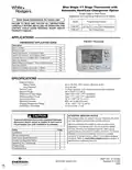
Blue Single 1/1 Stage Thermostat with  
Automatic Heat/Cool Changeover Option  
Single Stage or Heat Pump  
Installation and Operating Instructions for Model:  
Save these instructions for future use!  
Model  
Programming Choices  
FAILURE TO READ AND FOLLOW ALL INSTRUCTIONS  
CAREFULLY BEFORE INSTALLING OR OPERATING THIS  
CONTROL COULD CAUSE PERSONAL INJURY AND/OR  
PROPERTY DAMAGE.  
1F80-0471  
1F86-0471  
5/2 Day 5/1/1 Day Non-Programmable  
Non-Programmable  
APPLICATIONS  
1F80-0471 Thermostat  
THERMOSTAT APPLICATION GUIDE  
Description  
Gas or Oil Heat  
Yes  
Yes  
Yes  
No  
Electric Furnace  
Heat Pump (No Aux. or Emergency Heat)  
Heat Pump (with Aux. or Emergency Heat)  
Systems with up to 3 Stages Heat, 2 Stages Cool  
Heat Only Systems  
No  
Yes  
Yes  
Yes  
Yes  
Yes  
Millivolt Heat Only Systems – Floor or Wall Furnaces  
Cool Only Systems  
Hydronic (Hot Water) Zone Heat – 2 Wires  
Hydronic (Hot Water) Zone Heat – 3 Wires  
SPECIFICATIONS  
Electrical Rating:  
Battery Power. . . . . . . . . . . . . . . . . . . . . . . . . . mV to 30 VAC, NEC Class II, 50/60 Hz or DC  
Input-Hardwire . . . . . . . . . . . . . . . . . . . . . . . . . 20 to 30 VAC  
Terminal Load . . . . . . . . . . . . . . . . . . . . . . . . . . . . . 1.0 A per terminal, 1.5A maximum all terminals combined  
Setpoint Range . . . . . . . . . . . . . . . . . . . . . . . . . . . . 45° to 90°F (7° to 32°C)  
Differential (Single Stage) . . . . . . . . . . . . . . . . . . . . Heat 0.6°F; Cool 1.2°F (adjustable)  
Differential (Heat Pump) . . . . . . . . . . . . . . . . . . . . . Heat 1.2°F; Cool 1.2°F (adjustable)  
Operating Ambient. . . . . . . . . . . . . . . . . . . . . . . . . . 32° to +105°F (0° to +41°C)  
Operating Humidity . . . . . . . . . . . . . . . . . . . . . . . . . 90% non-condensing max.  
Shipping Temperature Range . . . . . . . . . . . . . . . . . -4° to +150°F (-20° to +65°C)  
Dimensions Thermostat. . . . . . . . . . . . . . . . . . . . . . 3.4"H x 4.4"W x 1.3"D  
ATTENTION: MERCURY NOTICE  
This product does not contain mercury. However, this prod-  
uct may replace a product that contains mercury.  
CAUTION  
Topreventelectricalshockand/orequipmentdamage,  
disconnect electric power to system at main fuse or  
circuit breaker box until installation is complete.  
!
Mercury and products containing mercury must not be  
discarded in household trash. Do not touch any spilled  
mercury. Wearing non-absorbent gloves, clean up any  
spilled mercury and place in a sealed container. For proper  
disposal of a product containing mercury or a sealed  
container of spilled mercury, place it in a suitable shipping  
container. Refer to www.white-rodgers.com for location to  
send product containing mercury.  
Index  
Installation  
Page  
2
2
3
4
6
6
8
Wiring Connections  
Thermostat Quick Reference  
Installer Configuration Menu  
Operating Your Thermostat  
Programming  
Troubleshooting  
PART NO. 37-6749D  
Replaces 37-6749C  
0902  
GeneralDetails
NameWHITE-RODGERS 1F86-0471 Blue Single 1 1 Stage Thermostat Instruction Manual
MakeWHITE RODGERS
LanguageEnglish
FiletypePDF (Download)
File size0.51 MB
Download PDF
1 Star2 Stars3 Stars4 Stars5 Stars (1 votes, average: 5.00 out of 5)
Loading...
White-Rodgers 1E78 Non Programmable Heat Only Thermostat User Manual
White-Rodgers 1F97-1277 Big Blue Single Stage Thermostat User Manual
White-Rodgers 1F56N-444 Thermostat User Manual
White-Rodgers 1F83-277 Heating & Air Conditioning Auto Changeover Heat Pump Thermostat User Manual
White-Rodgers M30 Thermostat Instruction Manual
WHITE-RODGERS 1F51N-619 Low Voltage Evaporative Cooler Thermostat Instruction Manual
White Rodgers 1F78-151 Non Programmable Thermostat Instructions
WHITE RODGERS 1F80-51 Programmable Electronic Digital Thermostat Instruction Manual
WHITE-RODGERS 1F90-71 5-Day 2-Day Electronic Digital Thermostat Instruction Manual
WHITE-RODGERS 1F95-1277 Universal Thermostat Owner’s Manual

WHITE-RODGERS 1F86-0471 Blue Single 1 1 Stage Thermostat Instruction Manual
Get the free PDF manual for the WHITE-RODGERS 1F86-0471 Blue Single 1 1 Stage Thermostat Instruction Manual and access setup steps, usage instructions, and troubleshooting tips. 👉 View online or download now to keep your thermostat running smoothly!
WHITE-RODGERS 1F86-0471 Blue Single 1 1 Stage Thermostat Instruction Manual Overview
Summary of Contents

  • Page 1: Blue single 1/1 stage thermostat with automatic heat/cool changeover option. Single stage or heat pump installation and operating instructions for model. Save these instructions for future use. Failure to read and follow all instructions could cause personal injury and/or property damage. Thermostat application guide includes various heating systems. Electrical rating: battery powered, 20 to 30 VAC input. Setpoint range: 45° to 90°F (7° to 32°C). Operating humidity: 90% non-condensing max. This product does not contain mercury but may replace a product that does. To prevent electrical shock and/or equipment damage, disconnect electric power to the system before installation.
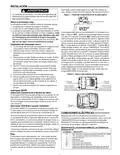
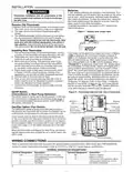
  • Page 2: Installation Batteries are included in the thermostat. To install the batteries, pull the battery door and lift open. Thermostat installation shall conform to Class II circuits per the NEC code. To replace the batteries, set the system to OFF. A standard heat/cool thermostat consists of three basic parts: the cover, the base, and the switching subbase. Before removing wires from the old thermostat, label each wire with the terminal designation. Thermostat can be powered by system AC power or battery. The SS/HP switch is factory set to the SS position for conventional single stage. The GAS/ELEC switch is factory set to the GAS position. Refer to equipment manufacturers' instructions for specific system wiring information.
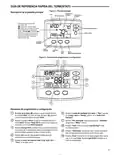
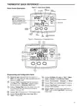
  • Page 3: Thermostat quick reference Home screen description includes room, time, temperature, and setting. Displays the power level of the 2 AA batteries. Indicates good power level or low battery status. Flame icon is displayed when the system is in heat mode. Snowflake icon is displayed when the system is in cool mode. Displays fan mode or Run in menu mode. The word Hold is displayed when the thermostat is in hold mode. Displays Change Filter when it's time to change or clean your filter. Displays system mode or Time in menu mode.
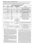
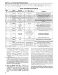
  • Page 4: Installer/configuration menu allows access to various settings. Press the Menu button for at least 5 seconds to enter the menu. Reversing valve output must be set according to the heat pump position. Cool savings is an optional feature that can reduce cooling costs. Selectable programs per week can be configured for programmable thermostats. Adjustable anticipation settings are available for heat, cool, and heat pump modes. Compressor lockout time settings can be configured. Display light options can be selected on or off. Temperature display can be set to Fahrenheit or Celsius. Filter change-out indicator settings are available.
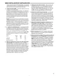
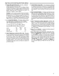
  • Page 5: Installer/configuration menu Energy management recovery is skipped if configured to be non-programmable. System mode configuration allows for various settings including heat and cool with auto changeover. Energy management recovery enables early heating or cooling to reach the program setpoint. Backlight display improves visibility in low lighting conditions and can be set to stay on continuously or momentarily. Cycle rate selection has factory default settings for medium and fast cycles for heat and cool. Temperature display adjustment allows for a change of up to 4° higher or lower from the calibrated factory setting. Selection of Fahrenheit or Celsius readout is available as required. Filter replacement reminder can be set to notify when it's time to change or clean the air filter. Compressor lockout feature helps protect the compressor from short cycling by waiting 5 minutes between cooling cycles.
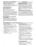
  • Page 6: Operating your thermostat Choose the fan setting (Auto or On) Fan Auto runs the fan only when the heating or cooling system is on. Fan On runs the fan continuously for increased air circulation. The HOLD feature bypasses the program and allows you to adjust the temperature manually. Choose the system setting (Heat, Off, Cool, Auto). Auto Changeover allows the thermostat to automatically select heating or cooling. Manual operation for non-programmable thermostats mode. Set current time and day for programming. Press Menu and then Time button to set the heating program. When programming is complete, press Run Schedule to activate your program.
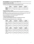
  • Page 7: Programming (for programmable model only) Energy saving factory pre-program The 1F80-0471 thermostats are programmed with energy saving settings for all days of the week. If this program suits your needs, simply set the thermostat clock and press the RUN button. The table shows the factory set heating and cooling schedule for all days of the week. Planning your program – important The 1F80-0471 comes configured for 5/2 day programming and can also be configured for 5+1+1 programming. Keep the following guidelines in mind when planning your program. In heating, lower temperatures will save energy. In cooling, higher temperatures will save energy. If you plan on using auto changeover, do not program the heating higher than the cooling.
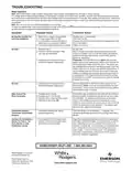
  • Page 8: Troubleshooting Reset operation When thermostat is reset, installer configuration menu settings and programming will reset to factory settings. If a voltage spike or static discharge blanks out the display or causes erratic thermostat operation, you can reset the thermostat by removing the wires from terminals R and C and removing batteries for 2 minutes. If the thermostat has been reset and still does not function correctly, contact your heating/cooling service person or place of purchase. No heat/no cool/no fan (common problems) Blown fuse or tripped circuit breaker. Furnace power switch to OFF. Furnace blower compartment door or panel loose or not properly installed. Pilot light not lit. Furnace lock-out condition. Heating system requires service or thermostat requires replacement. Cooling system requires service or thermostat requires replacement. Heat, cool or fan runs constantly. Thermostat thermometer setting requires adjustment. Furnace (air conditioner) cycles too fast or too slow.
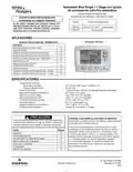
  • Page 9: Termostato Blue Single 1/1 Stage con opción de conmutación calor/frío automática. Instrucciones de instalación y uso para el modelo. Conserve estas instrucciones para consultarlas en cualquier momento. El no leer y seguir con cuidado todas las instrucciones antes de instalar o utilizar este control podría causar lesiones personales y/o daños materiales. Aplicaciones del termostato 1F80-0471. Especificaciones eléctricas del termostato. Características eléctricas incluyen alimentación con pilas y rango de temperatura de referencia. Precaución sobre el contenido de mercurio. Desconecte la alimentación eléctrica en la caja de fusibles o disyuntores principal hasta que haya finalizado la instalación del sistema. Índice de contenido del manual.
  • Page 10: Instalación La instalación del termostato y de todos los componentes del sistema de control debe ajustarse a las normas del código NEC para los circuitos Clase II. Un termostato de calor/frío estándar consta de tres partes básicas: la cubierta, la base y la subbase de conmutación. Antes de retirar los cables del termostato viejo, identifique cada cable con la designación de la terminal de la que lo desconectó. El termostato puede funcionar con la alimentación CA del sistema o con pilas. Instalación del termostato nuevo. Coloque la base sobre el orificio de la pared y marque las ubicaciones de los orificios de montaje usando la base como plantilla. Recomendamos cambiar las pilas cada 2 años. Fije bien la base a la pared utilizando los orificios de montaje y dos tornillos de montaje. El interruptor SS/HP viene ajustado de fábrica en la posición SS. Si su sistema requiere que el termostato active el ventilador circulador en una llamada de calor, el interruptor debe ajustarse en la posición ELEC.
  • Page 11: guía de referencia rápida del termostato Descripción de la pantalla principal Temperatura ambiente Temperatura de ajuste Día de la semana Muestra el nivel de carga de las 2 pilas AA Indica buen nivel de carga Indica que la carga de las pilas es baja Elementos de programación y configuración Muestra el modo del ventilador (On, Auto) o Run (ejecutar) en el modo HEAT.
  • Page 12: Menú instalador/de configuración Con el termostato en Heat, Cool o Auto, en operación normal, presione el botón Menu durante 5 segundos como mínimo. La pantalla mostrará la opción 1 tal como se describe en la siguiente tabla. Los elementos sombreados no están disponibles en el modelo 1F86. Cool Savings es una función de ahorro de energía opcional que puede reducir sus costos de enfriamiento. Cool Savings ajusta muy lentamente la temperatura de referencia para que se acerque más a la temperatura visualizada en pantalla. Cuando Cool Savings está realizando ajustes, aparecerá la palabra Save junto a la temperatura de referencia. Este control puede configurarse para los modos de programación de 5/2 días o 5/1/1 días, o para el modo no programable. El ajuste predeterminado es P2, que corresponde a la opción de programación de 5/2 días. La elección de 0 días para el modo no programable eliminará la necesidad de EMR y se pasará por alto ese paso en el menú. Si se selecciona On, presione MENU para seleccionar el ajuste de la función para el modo Cool.
  • Page 13: Menú instalador/de configuración Configuración del modo del sistema – Este termostato está configurado para calor y frío con opción predeterminada de conmutación automática. Control de energía (EMR) – Cuando el control de energía está activado, el termostato inicia la calefacción o el enfriamiento antes de la hora prevista. Selección de la luz de fondo de la pantalla – La luz de fondo mejora el contraste de la pantalla en condiciones de poca luz. Selección del ajuste de la pantalla de temperatura – Permite ajustar la visualización de la temperatura ambiente 4° más arriba o más abajo. Selección de velocidad de ciclo – El ajuste predeterminado de fábrica es ciclo medio para calor y ciclo rápido para frío. Selección de lectura en °F o °C – Cambia la unidad en que aparece la temperatura en la pantalla. Selección de aviso de cambio de filtro y ajuste de tiempo de funcionamiento – Permite activar un recordatorio para cambiar o limpiar el filtro de aire. Selección de bloqueo del compresor (CL) – Si se selecciona CL ON, el termostato esperará 5 minutos entre ciclos de enfriamiento.
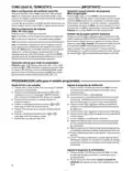
  • Page 14: cómo usar el termostato importante operación manual (omisión del programa) modo programable elija la configuración del ventilador (Auto/On) la función HOLD pasará por alto el programa y le permitirá ajustar la temperatura manualmente. la opción On hace funcionar el ventilador de forma continua. elija la configuración del sistema (Heat, Off, Cool, Auto) omisión del programa (omisión temporal) programación (sólo para el modelo programable)
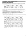
  • Page 15: Pre-programación de ahorro de energía de fábrica Los termostatos 1F80-0471 están programados con los ajustes de ahorro de energía indicados en la siguiente tabla para todos los días de la semana. La siguiente tabla muestra la programación de calefacción y enfriamiento ajustada de fábrica para todos los días de la semana. Los programas de calefacción y enfriamiento permiten ingresar sus propias horas y temperaturas de programación. El termostato 1F80-0471 viene configurado para programación de 5/2 días y también puede configurarse para programación de 5+1+1 días. Si desea reprogramar con un programa de 5/2 días, ingrese sus propias horas y temperaturas directamente a continuación. Si desea reprogramar con un programa de 5+1+1 días, complete todas las líneas con las horas y temperaturas que desea. En calefacción, las temperaturas más bajas ahorran energía. En enfriamiento, las temperaturas más altas ahorran energía. Si tiene pensado usar la opción de conmutación automática, no programe la temperatura de calefacción por encima de la de enfriamiento.
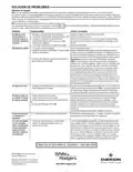
  • Page 16: solución de problemas operación de reajuste una vez reajustado el termostato, la configuración del menú instalador/de configuración y la programación volverán a los ajustes de fábrica. si un pico de voltaje o una descarga estática pone en blanco la pantalla o hace que el termostato funcione de manera errática, puede reajustar el termostato. si el termostato se ha reajustado pero aún no funciona correctamente, póngase en contacto con su servicio técnico de calefacción/enfriamiento. asegúrese de revisar los ajustes del menú instalador/de configuración. el sistema no calienta/el sistema no enfría/no funciona el ventilador (problemas comunes). la luz piloto no está encendida. la conexión al termostato o al sistema está suelta. el sistema de calefacción requiere servicio técnico o debe cambiarse el termostato. el ajuste del termostato no coincide con el termómetro.