Home > Danfoss > Danfoss CET B-RF Wireless Electronic Hot Water Cylinder Thermostat Installation Guide
Danfoss CET B-RF Wireless Electronic Hot Water Cylinder Thermostat Installation Guide
| General | Details |
|---|---|
| Name | Danfoss CET B-RF Wireless Electronic Hot Water Cylinder Thermostat Installation Guide |
| Make | Danfoss |
| Language | English |
| Filetype | PDF (Download) |
| File size | 0.23 MB |

Danfoss RET-MD Electronic Intelligent Dial Setting Thermostat Installation Guide
Danfoss VICUQ24M Icon Programmable II Room Thermostat Installation Guide

Danfoss MBC 8000, MBC 8100 Heavy Duty Thermostat Installation Guide

Danfoss UT 72-UT 73 Universal Thermostat Installation Guide

Danfoss ECtemp 530 Electronic Thermostat Installation Guide

Danfoss 014G0251 Eco Radiator Thermostat User Guide

Danfoss 014G0013 Z Wave Radiator Thermostat Installation Guide

Danfoss RET230P Electronic Thermostat Instruction Manual

Danfoss TP7000 Range Electronic 7 Day Programmable Room Thermostat Installation Guide

Danfoss RET1000 Series Electronic Thermostat User Guide

Danfoss CET B-RF Wireless Electronic Hot Water Cylinder Thermostat Installation Guide Overview
Summary of Contents
- Page 1: Wireless electronic hot water cylinder thermostat. User and installation instructions. Certification mark.
- Page 2: Installation Product overview Thermostat installation Receiver installation Schematics Commissioning User instructions What is a cylinder thermostat? Setting the temperature Battery replacement
- Page 3: Installation instructions The CET B-RF is a battery powered cylinder thermostat. It measures cylinder temperature using a strap-on temperature sensor. The sensor is fitted to the cylinder wall and wired to the thermostat. The thermostat is normally located adjacent to the cylinder. The thermostat and boiler or zone valve communicate using secure RF wireless communication. A receiver unit is mounted next to the boiler or control valve. The receiver responds to commands issued by the wireless thermostat.
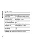
- Page 4: Product specification (Thermostat) Power supply: 2 x AA/LR6/MN1500 alkaline batteries Transmitter frequency: 433.92MHz Transmitter range: 30 metres line of sight Temperature range: 40 - 65°C Max. temp of thermostat: 45°C Design standard: EN60730-2-9 (EN300220 for RF) Dimensions, mm: 85 wide x 86 high x 42 deep Control pollution: Degree 2 Ball Hardness: 75°C Temperature accuracy: 1°C
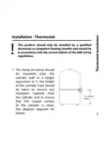
- Page 5: Installation should be performed by a qualified electrician or competent heating installer. Installation must comply with the current edition of the IEEE wiring regulations. The clamp on sensor should be mounted onto the cylinder wall at a height equivalent to half the height of the cylinder. Remove any insulation material from the cylinder before installation. Ensure that the copper surface of the cylinder is clean before mounting the sensor. Refer to the diagram for installation details.
- Page 6: Before attaching the sensor to the cylinder using the strap provided, connect a 2-core cable to the sensor to allow interconnection to the thermostat setting unit. Apply the contact paste provided to the part of the sensor in contact with the cylinder and clamp the sensor to the cylinder wall. A spacer piece is provided for use with cylinders that have thick insulation. Mount the thermostat wallplate on to a wall next to the cylinder. Connect the cable from the sensor to terminals 2 & 3 of the wallplate. Now mount the thermostat setting unit onto the wallplate and secure using the two screws on the bottom of the wallplate.
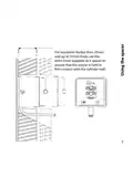
- Page 7: For insulation thicker than 25mm and up to 55mm thick, use the extra cover supplied as a spacer to ensure that the sensor is held in firm contact with the cylinder wall.
- Page 8: Cable specification: minimum cross section 0.5mm².
- Page 9: Installation - RX Receiver unit Mount the RX wallplate onto the wall with cable access from behind or below the wallplate. Typical wiring diagrams are shown on pages 11-14. Earth connections are for customer use only. The RX receiver may be mounted onto the wallplate and secured using the two screws. Ensure that there are no large metal obstructions between the thermostat and the RX receiver unit to avoid blocking radio communication.
- Page 10: Receiver wiring (RF only) includes RX1 and RX2C sections. For mains voltage operated systems, link terminal 2 to mains live supply. Power supply to the unit must not be switched by timeswitch. The RX1 section has terminals for electronics, COM, and zone controls. The RX2C section includes terminals labeled A, B, C, and additional zone controls. Zone 1 and Zone 2 have ON and OFF settings. The document outlines the basic wiring configuration for the receiver. It specifies the importance of proper connections for functionality. The layout indicates the arrangement of terminals for easy identification. The instructions emphasize safety and correct power supply management.
- Page 11: Hard wired heating with wireless hot water Control, 3 port mid-position valve
- Page 12: Wireless heating and hot water control. Using 2 x 2 port valves.
- Page 13: Hard wired heating with wireless hot water Control, 2 x 2 port valves
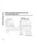
- Page 14: Wireless heating and hot water control with 3 port mid position valve. RX2C receiver - channel 1 paired to heating, channel 2 paired to CETB-RF. FP715 programmer. Boiler/pump. 3 port mid-position valve.
- Page 15: Commissioning instructions If the thermostat and receiver have been supplied together in a combined pack, the units have been paired in the factory and no commissioning is required. Ensure that the power to the RX1 is turned on and that the programmer is calling. Turn the thermostat dial so the widest end of the setting line is lined up with the LCD display. Remove the dial, press and hold the LEARN button for 3 seconds. Do not replace the setting dial yet.
- Page 16: Thermostat now transmits unique identity signal continuously for 5 minutes. Press and hold buttons PROG and CH1 until green LED light flashes once. For RX2C, repeat steps 2 and 3 for channel 2. Replace the thermostat dial, ensuring the widest end of the setting line is lined up with the LCD display.
- Page 17: Test the controls to ensure proper operation of the boiler, pump, and control valves. Set the thermostat to the required temperature. The temperature setting can be read from the LCD display.
- Page 18: What is a cylinder thermostat? A cylinder thermostat switches on and off the heat supply from the boiler to the hot-water cylinder. It works by sensing the temperature of the water inside the cylinder. The thermostat switches on the water heating when the temperature falls below the thermostat setting. It switches off once the set temperature has been reached. Turning a cylinder thermostat to a higher setting will not make the water heat up any faster. How quickly the water heats up depends on the design of the heating system.
- Page 19: The water heating will not work if a time switch or programmer has switched it off. The cylinder thermostat will not always switch the boiler off, as the boiler sometimes needs to heat the radiators. Cylinder thermostats are usually fitted between one quarter and one third of the way up the cylinder. The cylinder thermostat should be set at between 60°C and 65°C. This temperature is high enough to kill off harmful bacteria in the water. Raising the temperature of the stored hot water higher will result in wasted energy and increase the risk of scalding. If you have a boiler control thermostat, it should always be set to a higher temperature than that of the cylinder thermostat. In most boilers, a single boiler thermostat controls the temperature of water sent to both the cylinder and radiators. Some boilers may have two separate boiler thermostats.
- Page 20: User instructions Setting the temperature To alter the temperature that the thermostat controls, simply turn the setting dial on the thermostat. As the setting dial is moved, the small LCD display will show the selected temperature. In order to reduce the risk of Legionella infection, it is recommended that water be stored at not less than 60°C. Once the required temperature is set, the LCD display will show the temperature of the water in the cylinder close to the position where the sensor is located.
- Page 21: A small flame icon is lit in the display whenever the thermostat is calling for heat. The boiler will only run when both the thermostat and the time control are calling. Batteries will last in excess of two years. When batteries need to be changed, a battery icon will flash in the display. To change the batteries, loosen the two screws on the base of the thermostat and lift the thermostat off the base plate. Batteries are located in the rear of the thermostat unit and should be replaced using two high quality AA size alkaline cells.
- Page 22: Page 22
- Page 23: Page 23