
PRO1 T725 Thermostat User Guide
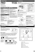


Installation Manual
Installation Tips
Wall Locations
The thermostat should be installed approximately 4 to 5 feet above the
floor. Select an area with average temperature and good air circulation.
T725
Pro1 Technologies
P.O. Box 3377
Springfield, MO 65808-3377
Do not install
thermostat in locations:
• Close to hot or cold air ducts
• That are in direct sunlight
• With an outside wall behind
the thermostat
Toll Free: 888-776-1427
Hours of Operation: M-F 9AM - 6PM Eastern
• In areas that do not require
conditioning
• Where there are dead spots
or drafts
(in corners or behind doors)
• Where there might be
concealed chimneys or
pipes
Power Type
Thermostat Application Guide
Battery Power
Description
Hardwire (Common Wire)
Hardwire (Common Wire) with
Battery Backup
Gas or Oil Heat
Yes
Yes
Yes
Yes
Electric Furnace
Heat Pump (No Aux. or Emergency Heat)
Heat Pump (With Aux. or Emergency Heat)
Multi-Stage Systems
Installation Tip
A trained, experienced
technician must install this
product.
Yes
Yes
Pick an installation location that is easy for
Heat Only Systems
the user to access. The temperature of the
location should be representative of the
building.
Heat Only Systems - Floor or Wall Furnace
Cool Only Systems
Yes
Yes
Carefully read these
instructions. You could damage
this product or cause a
Yes
No
Millivolt Conventional Systems
Two Transformer Systems
hazardous condition if you fail to
follow these instructions.
Subbase Installation
Table of Contents
Page
Installation Tips
2-3
4-5
6
Horizontal Mount
Vertical Mount
Installation Tip:
Electrical Hazard
Failure to disconnect the power before
beginning to install this product can
cause electrical shock or equipment
damage.
Thermostat Quick Reference
Wiring
Wiring Diagrams
Features & About The Badge
Technician Setup
Programming Thermostat
Una version en español de este
manual se puede descargar en
la pagina web de la compañia.
7
8
9 -12
13-16
Specifications
The display range of temperature ... 41˚F to 95˚F (5˚C to 35˚C)
The control range of temperature.... 44˚F to 90˚F (7˚C to 32˚C)
Swing (cycle rate or differential) ...... Heating is adjustable from 0.2˚ to 2.0˚
Cooling is adjustable from 0.2˚ to 2.0˚
Mercury Notice
All of our products are mercury free.
However, if the product you are
replacing contains mercury, dispose of
it properly. Your local waste
Power source ...........................................18 to 30 VAC, NEC Class II, 50/60 Hz
for hardwire
Battery power from 2 AA Alkaline
batteries
management authority can give you
instructions on recycling and proper
disposal.
Operating ambient ............................... 32˚F to +105˚F (0˚C to +41˚C)
Operating humidity .............................. 90% non-condensing maximum
Dimensions of thermostat ................. 4.7”W x 4.4”H x 0.8”D
For vertical mount put one screw on the top
and one screw on the bottom.
For horizontal mount put one screw on the
left and one screw on the right.
U.S. Registered Trademark. Patents pending
Copyright 2017 All Rights Reserved.
Rev. 1751
Installation Tips
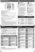
Thermostat Quick Reference
Mount Thermostat
Getting to know your thermostat
Align the 4 tabs on the subbase with
corresponding slots on the back of the
thermostat, then push gently until the
thermostat snaps in place.
Battery Installation
Battery installation is recommended even if thermostat is hardwired
(C terminal connected). When thermostat is hardwired and batteries
are installed, the thermostat will activate a compressor delay of 5
minutes when the thermostat detects a power outage from the
hardwired power supply.
Important:
High quality alkaline batteries are recommended.
Rechargeable batteries or low quality batteries
do not guarantee a 1-year life span.
Insert 2 AA
Alkaline batteries
(included). High
quality alkaline
batteries are
recommended.
Simple
operating
instructions
are found
on the back
of the
LCD Display
Glow in the dark light button
Fan Switch
battery
door.
System Switch
Easy change battery door
Temperature Setpoint Buttons


| General | Details |
|---|---|
| Name | PRO1 T725 Thermostat User Guide |
| Make | PRO1 |
| Language | English |
| Filetype | PDF (Download) |
| File size | 0.38 MB |
 (1 votes, average: 5.00 out of 5)
 Loading...

PRO1 T751i Thermostat Installation Guide

PRO1 T731W Wireless PTAC Non-Programmable Thermostat Installation Guide

PRO1 T805 Non Programmable Thermostat Instruction Manual

PRO1 T701 Digital Non Programmable Thermostat Instruction Manual

PRO1 IAQ T721i Digital WIFI Programmable Thermostat User Manual

PRO1 R250W Wireless System Thermostat Owner’s Manual

PRO1 T755 Heat 2 Cool Dual Fuel Thermostat User Manual

PRO1 T771 Programmable Electronic Thermostat Instructions

PRO1 T725 Thermostat User Guide Overview
Summary of Contents
- Page 1: Installation tips include selecting a location approximately 4 to 5 feet above the floor with average temperature and good air circulation. Avoid installing the thermostat close to hot or cold air ducts, in direct sunlight, or with an outside wall behind it. Do not place the thermostat in areas that do not require conditioning or where there are dead spots or drafts. A trained technician must install the product to prevent damage or hazardous conditions. The installation location should be easily accessible for the user and representative of the building's temperature. Electrical hazards can occur if power is not disconnected before installation. The display range of temperature is 41˚F to 95˚F, and the control range is 44˚F to 90˚F. All products are mercury-free, and proper disposal is required for products containing mercury. Battery installation is recommended even if the thermostat is hardwired, as it activates a compressor delay during power outages. High-quality alkaline batteries are necessary for optimal performance and longevity.
- Page 2: Thermostat quick reference Getting to know your thermostat Caution: electrical hazard Failure to disconnect the power before beginning to install this product can cause electrical shock or equipment damage. All components of the control system and the thermostat installation must conform to Class II circuits per the NEC Code. Do not overtighten terminal block screws, as this can damage the terminal block. The low battery indicator is displayed when the AA battery power is low. This thermostat has 4 programmable time periods per day. The swing setting is adjustable and affects the frequency of cycles. This feature allows you to set a maximum heat setpoint value. The compressor short cycle delay protects the compressor from short cycling.
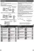
- Page 3: Wiring diagrams Features & private label badge Temporary and permanent hold feature Power supply Use either O or B terminals for changeover valve. Optional 24 VAC common connection when thermostat is used in battery power mode. When cool or heat is turned on, the thermostat will display HOLD and RUN SCHED. Temporary hold: The temperature will remain at this setpoint temporarily until the next time period. Permanent hold: Press the HOLD key to see HOLD appear below the setpoint temperature. To return to running schedule: Press the RUN SCHED button to exit either temporary or permanent hold. Filter change reminder: You will see FILT in the display when your air filter needs to be changed.
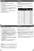
- Page 4: Set Time All of our programmable thermostats are shipped with an energy saving pre-program. You can customize this default program by following the steps on page 15. There are four time periods for each program (WAKE, LEAVE, RETURN, SLEEP). To customize your program schedule, follow these steps. If using 7-Day Programming use previous steps for every individual day. You have to program heat and cool each separately. Press the MENU button (If menu does not appear first press RUN SCHED). You are now programming the wake time period for that day. To copy ALL time periods and temperatures of current system and day to ALL days, Press and Hold 2nd button down on left until the Days and Time flash. Repeat steps 4 through 7 for the Saturday WAKE time period, LEAVE time period, RETURN time period, and for the Saturday SLEEP time period.

SUNTOUCH SunStat 1140-01 R4 Relay Thermostat User Manual

LUX TX9600TSA Smart Temp Universal 7 Day Programmable Touchscreen Thermostat Instruction Manual

EPH CONTROLS RDTP-24 24V Recessed Room Thermostat Instruction Manual

EBECO EB-Therm 500 Floor Heating Thermostat Instruction Manual

SALUS Fan Coil thermostat FC600 User Guide

EPH Controls RFCP RF Cylinder Thermostat Instruction Manual

Fudajo 52429 Chick Heating Plate with Thermostat Instruction Manual
STELPRO STE241 Low Voltage 24V Electronic Thermostat User Guide

GENERAL MITRA 220 RF Digital Room Thermostat User Manual

Danfoss CET2000B-RF + RX1-S + CS2 Thermostat User Guide