
PRO1 T725 Thermostat User Guide


Wiring Diagrams
Features & Private Label Badge
(If using programming)
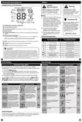
Temporary and Permanent Hold Feature
Power supply
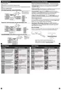
Use either O or B terminals for changeover valve.
Optional 24 VAC common connection when thermostat is used in battery power mode.
Factory-supplied jumper
When cool or heat is turned on, the thermostat will display HOLD
and RUN SCHED on the left of your screen when you press the
or button.
Temporary Hold: At this time if you do nothing, the temperature will
remain at this setpoint temporarily until next time period.
2H/1C Heat Pump System - Factory Default Setting
Permanent Hold: If you press the HOLD key on the left of your
screen, you will see HOLD appear below the setpoint temperature in
the display. The thermostat will now permanently stay at this
C
Note: In many systems
with no emergency heat
relay a jumper can be
used between E and W2.
L2
L1(HOT)
setpoint and can be adjusted using the
or
keys.
R
Y
R
COMPRESSOR
RELAY
To Return to Running Schedule: Press the RUN SCHED button on
the left of your screen to exit either temporary or permanent hold.
C
COOL CHANGE
OVER VALVE
W/E
G
O
B
FAN RELAY
AUXILIARY
Filter Change Reminder
HEAT CHANGE
OVER VALVE
W2
If your installing contractor has configured the thermostat to remind
you when the air filter needs to be changed, you will see FILT in the
display when your air filter needs to be changed.
Typical 2H/1C Heat Pump System with separate emergency heat
C
Resetting the filter change reminder: When FILT reminder is
displayed, you should change your air filter and reset the reminder
by holding down the second button from the top left side of the
thermostat for 3 seconds.
L2
L1(HOT)
R
R
COMPRESSOR
RELAY
Y
C
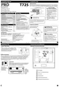
About The Badge
COOL CHANGE
OVER VALVE
O
B
All of our thermostats use the same universal magnetic badge. Visit the
company website to learn more about our free private label program.
EMERGENCY
RELAY
W/E
G
HEAT CHANGE
OVER VALVE
FAN RELAY
AUXILIARY
W2
Use the bevel on lower ridge
Conventional System 1H/1C, 2H/1C (Heat pump set to“OFF”in tech settings)
C
Note: This
thermostat is only
compatible with
ONE transformer
systems.
L2
L1(HOT)
Magnet in door
R
Y
R
COMPRESSOR
RELAY
C
W/E
G
Gently slide a screwdriver into the bottom edge of the
badge. Gently turn the screwdriver counter clockwise. The
badge is held on by a magnet in the well of the battery door.
The badge should pry off easily. DO NOT USE FORCE.
HEAT RELAY
FAN RELAY
W2
HEAT RELAY 2
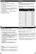
Tech Settings
Tech Settings
Tech Settings
Tech Settings
LCD Will Show Adjustment Options
Default
LCD Will Show Adjustment Options
Default
Select GAS for systems that
EL - Electric for thermostat
control
This feature will start heating and
Use the and
ON or OFF.
key to turn
control the fan during a call for
heat. Select ELEC to have the
thermostat control the fan during a
call for heat.
Next Step
Next Step
cooling early to bring the building
temperature to its programmed
setpoint by the begining of the
WAKE or RETURN time period.
Fan
Operation
Pro
Recovery
EL
ON
GS- Gas for system control
Prev Step
Next Step
Prev Step
You can configure this thermostat
to have 7 Day, 5+1+1 program-
ming or non programmable.
Use the and key to se-
lect 7d for 7 Day, 5d for 5+1+1,
or 0d for non programmable.
This feature controls the number of
stages in Emergency Heat mode. It
only appears if the Technician Setup
Step for HEAT PUMP is ON.
Use the
1-stage or 2-stage operation.
or
key to select
Emergency
Heat
Stages
Next Step
Program
Options
5d
1
Prev Step
Next Step
Prev Step
Next Step
When set to ON this thermostat
will operate a heat pump system
(default). If set to OFF this
thermostat will operate a
conventional system, and the next
tech step will not appear.
ON - Configured to operate heat
pump system.
OFF - Configured to operate
conventional system
See page 6 for terminal
designations.
This feature allows the thermostat to
keep multiple stages of heat
energized until setpoint is satisfied.
Use the
ON or OFF.
or
or
key to turn
Heat Pump
Satisfy
Setpoint
ON
OFF
OFF
Prev Step
Next Step
Prev Step
Next Step
This feature allows a delay to occur
when a second stage is needed.
This allows the previous stage extra
time to satisfy setpoint.
Use the
key to
OFF Will allow Y(1st stage of Heat)
and W2 (Aux Heat) to run together
if called for.
For Dual Fuel applications (Gas/
Fossil fuel Auxiliary Heat), turn this
setting ON to LOCKOUT the Heat
Pump (Y) when Auxiliary Heat (W2)
is on. If desired- This can also be used
with Electric Auxiliary.
select OFF, 5, 10, 15, 30, 45, 60,
or 90 minutes.
Dual Fuel
Auxiliary
for Heat
Pump
Staging
Delay
OFF
ON Will de-energize Y terminal
45 seconds after a call for Auxiliary
Heat (W2).
Prev Step
Prev Step
Will only
appear if
Heat pump
setting is
turned ON.

| General | Details |
|---|---|
| Name | PRO1 T725 Thermostat User Guide |
| Make | PRO1 |
| Language | English |
| Filetype | PDF (Download) |
| File size | 0.38 MB |
 (1 votes, average: 5.00 out of 5)
 Loading...

PRO1 T751i Thermostat Installation Guide

PRO1 T731W Wireless PTAC Non-Programmable Thermostat Installation Guide

PRO1 T805 Non Programmable Thermostat Instruction Manual

PRO1 T701 Digital Non Programmable Thermostat Instruction Manual

PRO1 IAQ T721i Digital WIFI Programmable Thermostat User Manual

PRO1 R250W Wireless System Thermostat Owner’s Manual

PRO1 T755 Heat 2 Cool Dual Fuel Thermostat User Manual

PRO1 T771 Programmable Electronic Thermostat Instructions


INKBIRD ITC-306A Digital Thermostat User Manual

BEOK TDS21WIFI-AC Fan Coil Thermostat Instruction Manual

STELPRO STZW402 – KI Electronic Thermostat Owner’s Manual

COMPUTHERM Q20 Programmable Digital Room Thermostat Instruction Manual

NEOMITIS Rtaneoa Wired Analog Room Thermostat Instruction Manual
terneo rzx Smart Thermostat User Manual

NIBE RMU S40 Room Thermostat Instruction Manual

Google G953-01573-01-A Nest 4th Gen Smart Wi-Fi Thermostat Owner’s Manual

PowerOptimal Elon Smart Thermostat User Guide

EBECO EB-Therm 205 Thermostat User Guide