Home > WHITE RODGERS > White-Rodgers 1F97-1277 Big Blue Single Stage Thermostat User Manual

White-Rodgers 1F97-1277 Big Blue Single Stage Thermostat User Manual
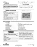
Big Blue Single Stage Thermostat with  
Automatic Heat/Cool Changeover Option  
Single Stage Installation and Operating  
Instructions for Model:  
Save these instructions for future use!  
FAILURE TO READ AND FOLLOW ALL INSTRUCTIONS  
CAREFULLYBEFOREINSTALLINGOROPERATINGTHIS  
CONTROL COULD CAUSE PERSONAL INJURY AND/OR  
PROPERTY DAMAGE.  
Model  
Programming Choices  
Non-Programmable 5/1/1 Day  
7 Day  
1F97-1277  
APPLICATIONS  
THERMOSTAT APPLICATION GUIDE  
1F97-1277 Touchscreen Thermostat  
Description  
Heat Pump (No Aux. or Emergency Heat)  
Heat Pump (with Aux. or Emergency Heat)  
Systems with up to 3 Stages Heat, 2 Stages Cool  
Heat Only Systems  
No  
No  
No  
Yes  
Yes  
Yes  
Yes  
Yes  
Yes  
Yes  
Yes  
No  
Millivolt Heat Only Systems – Floor or Wall Furnaces  
Cool Only Systems  
Gas or Oil Heat  
Electric Furnace  
Hydronic (Hot Water) Zone Heat – 2 Wires  
Hydronic (Hot Water) Zone Heat – 3 Wires  
Wired Remote Temperature Sensor (Indoor/Outdoor)  
Dual Fuel Feature (Heat Pump Mode)  
SPECIFICATIONS  
Electrical Rating:  
Battery Power. . . . . . . . . . . . . . . . . . . . . . . . . . mV to 30 VAC, NEC Class II, 50/60 Hz or DC  
Input-Hardwire . . . . . . . . . . . . . . . . . . . . . . . . . 20 to 30 VAC  
Terminal Load . . . . . . . . . . . . . . . . . . . . . . . . . . . . . 1.5A per terminal, 2.5A maximum all terminals combined  
Setpoint Range . . . . . . . . . . . . . . . . . . . . . . . . . . . . 45 to 99°F (7 to 37°C)  
Differential (Single Stage) . . . . . . . . . . . . . . . . . . . . Heat 0.6°FF Cool 1.2°F  
Differential (Multi-Stage) . . . . . . . . . . . . . . . . . . . . . Heat 0.6°FF Cool 1.2°F  
Differential (Heat Pump) . . . . . . . . . . . . . . . . . . . . . Heat 1.2°FF Cool 1.5°F  
Operating Ambient. . . . . . . . . . . . . . . . . . . . . . . . . . 32°F to +105°F (0 to +41°C)  
Operating Humidity . . . . . . . . . . . . . . . . . . . . . . . . . 90% non-condensing max.  
Shipping Temperature Range . . . . . . . . . . . . . . . . . -4 to +150°F (-20 to +65°C)  
Dimensions Thermostat. . . . . . . . . . . . . . . . . . . . . . 4-9/16"H x 5-13/16"W x 1-3/16"D  
ATTENTION: MERCURY NOTICE  
This product does not contain mercury. However, this  
product may replace a product that contains mercury.  
CAUTION  
To prevent electrical shock and/or equipment damage,  
disconnect electric power to system at main fuse or  
circuit breaker box until installation is complete.  
!
Mercury and products containing mercury must not be  
discarded in household trash. Do not touch any spilled  
mercury. Wearing non-absorbent gloves, clean up any  
spilled mercury and place in a sealed container. For proper  
disposal of a product containing mercury or a sealed  
container of spilled mercury, place it in a suitable shipping  
container. Refer to www.thermostat-recycle.org for  
location to send the product containing mercury.  
Index  
Installation  
Page  
2
2
Wiring Connections  
Thermostat Quick Reference  
Installer Configuration Menu  
Operating Your Thermostat  
Programming  
4
5
8
9
Troubleshooting  
12  
PART NO. 37-6814C  
Replaces 37-6814B  
1150  
GeneralDetails
NameWhite-Rodgers 1F97-1277 Big Blue Single Stage Thermostat User Manual
MakeWHITE RODGERS
LanguageEnglish
FiletypePDF (Download)
File size0.49 MB
Download PDF
1 Star2 Stars3 Stars4 Stars5 Stars (1 votes, average: 5.00 out of 5)
Loading...
White-Rodgers 1E78 Non Programmable Heat Only Thermostat User Manual
White-Rodgers 1F56N-444 Thermostat User Manual
White-Rodgers 1F83-277 Heating & Air Conditioning Auto Changeover Heat Pump Thermostat User Manual
White-Rodgers M30 Thermostat Instruction Manual
WHITE-RODGERS 1F51N-619 Low Voltage Evaporative Cooler Thermostat Instruction Manual
WHITE-RODGERS 1F95-1277 Universal Thermostat Owner’s Manual
White Rodgers 1F78-151 Non Programmable Thermostat Instructions
WHITE RODGERS 1F80-51 Programmable Electronic Digital Thermostat Instruction Manual
WHITE-RODGERS 1F86-0471 Blue Single 1 1 Stage Thermostat Instruction Manual
WHITE-RODGERS 1F90-71 5-Day 2-Day Electronic Digital Thermostat Instruction Manual

White-Rodgers 1F97-1277 Big Blue Single Stage Thermostat User Manual
Get the free PDF manual for the White-Rodgers 1F97-1277 Big Blue Single Stage Thermostat User Manual and access setup steps, usage instructions, and troubleshooting tips. 👉 View online or download now to keep your thermostat running smoothly!
White-Rodgers 1F97-1277 Big Blue Single Stage Thermostat User Manual Overview
Summary of Contents

  • Page 1: Big Blue Single Stage Thermostat with automatic heat/cool changeover option. Single stage installation and operating instructions for model 1F97-1277. Failure to read and follow all instructions could cause personal injury and/or property damage. Thermostat application guide includes various heating and cooling system types. Specifications detail electrical ratings, input hardwire, terminal load, and setpoint range. Operating ambient and humidity conditions are specified for optimal performance. Attention: This product does not contain mercury, but may replace a product that does. Caution: Disconnect electric power to the system before installation to prevent electrical shock. Index includes sections on installation, wiring connections, thermostat quick reference, and troubleshooting.
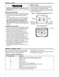
  • Page 2: INSTALLATION Battery location includes two AA alkaline batteries included in the thermostat with a battery tag to prevent power drainage. To replace batteries, set the system to OFF, remove the thermostat from the wall, and install the batteries in the rear along the top of the thermostat. Thermostat installation and all components of the control system shall conform to Class II circuits per the NEC code. A standard heat/cool thermostat consists of three basic parts: the cover, the base, and the switching subbase. Before removing wires from the old thermostat, label each wire with the terminal designation from which it was attached. Disconnect the wires from the old thermostat one at a time and do not let wires fall back into the wall. For installing a new thermostat, pull the thermostat body off the thermostat base carefully. Drill mounting holes and use plastic screw anchors if existing holes are too large. Connect wires to the terminal block on the base using the appropriate wiring schematic. Refer to equipment manufacturers' instructions for specific system wiring information.
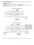
  • Page 3: Wiring connections This thermostat is designed to operate a single-transformer or two-transformer system. Refer to equipment manufacturers' instructions for specific system wiring information. After wiring, see the installer configuration section for proper thermostat configuration. You can configure the thermostat for use with single stage systems. If continuous backlight or hardwired power input are desired but do not function in both heat and cool modes, cut the heating transformer 24V wires and tape off. Disconnect the wire to the RH terminal and install a jumper between RH and RC. Common connection is required for fault or malfunction indication and remote sensor. Connection for call for service diagnostic indicator is compatible with mechanical or electronic condenser control with Comfort Alert.
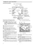
  • Page 4: Thermostat quick reference provides an overview of the home screen display, including room temperature, set temperature, and time of day. The UP/Down buttons are used for modifying the set point and navigating the menus. The fan switch allows users to enter a user-friendly program into the schedule. The menu key provides access to different modes such as configuration, set time, set schedule, and cleaning. The battery level indicator shows the current power level of the batteries and indicates when to replace them. Programming and configuration items are displayed, including keypad lockout and temperature limit features. The system on indicator shows when the heating or cooling stage is energized. The Change Filter reminder appears after the system has run for the programmed filter time period. The Cool Savings display indicates when the feature is enabled or active. Call For Service indicates a fault in the heating or cooling system.
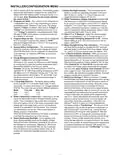
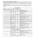
  • Page 5: Installer/configuration menu instructions are provided for accessing and navigating the menu. To enter the menu, press the Menu touch key and hold the Installer Config touch key for 5 seconds. Defaulting programming, clock, and configuration settings requires pressing specific keys simultaneously. The configuration menu includes various settings such as gas and electric options for furnace and thermostat control. Program settings allow for different configurations based on the number of programs per week and program periods per day. Energy management recovery can be selected with programming options enabled. Adjustable anticipation and cycle rates for heating and cooling can be configured. Temperature display units can be set to Fahrenheit or Celsius. Audible beeper and daylight saving time calculations can be enabled or disabled. Keypad lockout features and remote temperature sensor options are also included in the configuration settings.
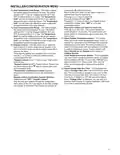
  • Page 6: Installer/configuration menu Gas or electric fan operation. If the heating system requires the thermostat to energize the fan, select electric. Programs per week can be configured for 7 independent days or 5/1/1 day programming or nonprogrammable modes. Select backlight intensity with two selectable options: high and low. Select temperature display adjustment from -4°F to +4°F in 1° steps. Select °F or °C readout; factory default is °F. Program steps per day can be configured for 4 or 2 program steps. Select audio prompting (beeper) on or off; factory default setting is on. Select daylight saving time calculation for automatic adjustment. Select automatic schedule to program a desired comfort temperature into all program periods. Select cool savings™ to reduce AC system running time during periods of high demand.
  • Page 7: Installer/configuration menu Heat temperature limit range adjusts the highest setpoint temperature for heat, with a default setting of 99°F. Cool temperature limit range adjusts the lowest setpoint temperature for cool, with a default setting of 45°F. Select remote temperature sensor allows one wired remote temperature sensor to be connected and indicates the measured temperature. Keypad lockout allows you to select the type of lockout or limited range security required, with three security settings available. Local temperature sensor disable is applicable only when the indoor remote temperature sensor is enabled. Select change filter run time sets a reminder to change or clean your air filter after a set time of blower operation. The time for filter change can be set from 25 to 1975 hours in 25-hour increments. Temperature limit/keypad lockout prevents changing the temperature limits in the configuration menu. The display will read Change Filter after the set time of blower operation. Pressing Clean Display clears the Change Filter indicator.
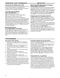
  • Page 8: Operating your thermostat Manual operation (bypassing the program) Choose the fan setting (Auto or On) Fan Auto runs the fan only when the heating or cooling system is on. Fan On runs the fan continuously for increased air circulation. The HOLD feature bypasses the program and allows you to adjust the temperature manually. Choose the system setting (Cool, Off, Heat, Auto) Program override (temporary override) allows you to adjust the temperature for a limited time. Auto changeover is used in areas where both heating and cooling may be required on the same day. Set current time and day for programming. Automatic daylight saving calculation adjusts the clock for daylight savings time.
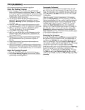
  • Page 9: Programming Automatic schedule allows programming every day with popular time and temperature profiles using one key press. Auto schedule options should be set on in the installer configuration. To enter the heating program, press the Menu button and then press Set Schedule. Select either Heat or Cool in the system switch area. Press the Auto Schedule touch key to insert the displayed temperature setpoint as the Comfort Temperature. The display will show the day(s) being programmed along with the time and set temperature. Use the FAN key to select fan operation during a program period. When programming is complete, press Run Schedule to activate the program. In Run mode, the fan will turn on during the complete period if FAN Prog is selected. To enter the cooling program, press the SYSTEM button until the Cool icon appears.
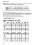
  • Page 10: Energy saving factory pre-program The 1F97-1277 thermostats are programmed with energy saving settings for all days of the week. If this program suits your needs, simply set the thermostat clock and press the RUN button. The table shows the factory set heating and cooling schedule for all days of the week. You can eliminate two program periods in the configuration menu if the building is occupied all day. The 1F97-1277 comes configured for 7 day programming and can also be configured for 5+1+1 programming. Factory settings are listed on Monday, Saturday, and Sunday. In heating, lower temperatures will save energy. In cooling, higher temperatures will save energy. If you plan on using auto changeover, do not program the heating higher than the cooling.
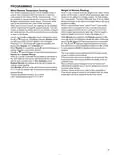
  • Page 11: Programming Weight of remote reading is displayed in view schedule mode. One remote temperature sensor can be installed indoor or outdoor. The sensor connects to the thermostat with a maximum cable length of 100 meters. The thermostat reads the sensor only when 24VAC is present. User can enable or disable the remote sensor in installer configuration mode. Pressing specific keys allows sequencing of the indoor remote temperature sensor weight. The local sensor may be disabled only if the indoor remote sensor is enabled. The actual temperature displayed is the weighted sum of local and indoor remote sensors. Outdoor temperature range is -40 to 140°F. Indoor temperature range is 32°F to 99°F.
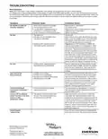
  • Page 12: Troubleshooting Reset operation: When the thermostat is reset, installer configuration menu settings and programming will reset to factory settings. If a voltage spike or static discharge causes erratic thermostat operation, reset the thermostat by removing the wires from terminals R and C and removing batteries for 2 minutes. No heat/no cool/no fan: Common problems include a blown fuse, tripped circuit breaker, or a loose connection to the thermostat or system. No heat: Possible causes include a pilot light not lit or a furnace lock-out condition. Diagnostic: Set the system switch to heat and raise the setpoint above room temperature to check thermostat operation. No cool: The cooling system may require service or thermostat replacement. Heat, cool, or fan runs constantly: Check for possible shorts in wiring or thermostat. Thermostat setting & thermometer disagree: The thermometer can be adjusted +/- 4 degrees. Furnace cycles too fast or too slow: The location of the thermostat may influence the cycle rate; adjustments can be made in the configuration menu. Forgot keypad lockout code: Press the menu button and hold for 20 seconds to unlock the thermostat.