
Home > WHITE RODGERS > White-Rodgers 1F83-277 Heating & Air Conditioning Auto Changeover Heat Pump Thermostat User Manual
White-Rodgers 1F83-277 Heating & Air Conditioning Auto Changeover Heat Pump Thermostat User Manual



MOUNTING AND WIRING
WARNING
CAUTION
Take care when securing and routing wires so they do
not short to adjacent terminals or rear of thermostat.
Personal injury and/or property damage may occur.
!
!
Do not use on circuits exceeding specified voltage.
Higher voltage will damage control and could cause
shock or fire hazard.
Attach Thermostat Base to Wall
Do not short out terminals on gas valve or primary
control to test. Short or incorrect wiring will damage
thermostat and could cause personal injury and/or
property damage.
1. Remove the packing material from the thermostat. Gently
pull the cover straight off the base. Forcing or prying on
the thermostat will cause damage to the unit.
2. Connect wires beneath terminal screws on base using
appropriate wiring schematic (see figs. 2 through 4).
Thermostat installation and all components of the
system shall conform to Class II circuits per the NEC
code.
3. Place base over hole in wall and mark mounting hole
locations on wall using base as a template.
4. Move base out of the way. Drill mounting holes.
Electric/Gas Switch (Fan Option)
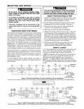
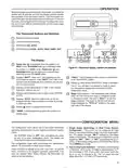
5. Fasten base loosely to wall, as shown in fig. 1, using two
mounting screws. Place a level against bottom of base,
adjust until level, and then tighten screws. (Leveling is for
appearance only and will not affect thermostat operation.)
If you are using existing mounting holes, or if holes drilled
are too large and do not allow you to tighten base snugly,
use plastic screw anchors to secure subbase.
This thermostat is configured from the factory to operate a heat/
cool, fossil fuel (gas, oil, etc.), forced air system. It is configured
correctly for any system that DOES NOT require the thermostat
to energize the fan on a call for heat. If you system is an electric
heat or heat-pump system that REQUIRES the thermostat to
turn on the fan on a call for heat, locate the ELEC/GAS switch
on the back of the thermostat (see fig. 1) and switch it to the
ELEC position. This will allow the thermostat to energize the fan
immediately on a call for heat. If you are unsure if the heating/
cooling system requires the thermostat to control the fan,
contact a qualified heating and air conditioning service person.
6. Push excess wire into wall and plug hole with a fire-
resistant material (such as fiberglass insulation) to
prevent drafts from affecting thermostat operation.
Battery Location
2 “AA” alkaline batteries are included in the thermostat at the
factory with a battery tag to prevent power drainage. You
must remove the battery tag to engage the batteries.
When the thermostat is configured for Heat Pump, the thermo-
stat will always power the circulator fan on a call for heat in the
HEAT mode. The ELEC/GAS switch must be set to match the
type of Auxiliary heat your system uses for proper operation in
the EMERgency mode.
If “BATT” is displayed, the batteries are low and should be
replaced. For best results, replace all batteries with new
premium brand alkaline batteries such as Duracell® or
Energizer®. To replace batteries, press system button to
OFF, install the batteries along the top of the base (see Fig.
1). The batteries must be installed with the positive (+) end to
the left.
All wiring diagrams are for typical systems only. Refer to
equipment manufacturers’ instructions for specific system wir-
ing information.
E/W1
THERMOSTAT
*
O
B
Y2
L
Y1
G
W2
C
R
SYSTEM
SYSTEM
MONITOR
SWITCH
Reversing Valve
Energized in Cool
Mode
Reversing Valve
Energized in Heat,
Off, Emergency
Mode
2nd Stage
Fan
Emergency
Heat
Relay
Compressor
Aux
Heat
Relay
Compressor
Contactor
Relay
Hot
24 VAC
120 VAC
Neutral
TRANSFORMER
(Class II Current Limited)
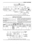
Figure 2.Typical wiring diagram for single transformer heat pump systems
*The 24 volt neutral connection to terminal C on the thermostat is not required if you replace the batteries once a year with fresh “AA” alkaline batteries.
NOTE
If safety circuits are in only one of the systems, remove
the transformer of the system with NO safety circuits.
E/W1
THERMOSTAT
*
O
B
Y2
L
Y1
G
W2
C
R
SYSTEM
CUT AND
TAPE OFF!
SYSTEM
MONITOR
SWITCH
Reversing
Valve
Reversing
Valve
2nd Stage
Fan
Limit or
Safety
Switches
Emergency
Heat
Relay
Compressor
Relay
HOT
Energized in
Heat, Off,
Emergency
Mode
Energized in
Cool Mode
24 VAC
Aux
Heat
Relay
120 VAC
NEUTRAL
Compressor
Contactor
Hot
24 VAC
120 VAC
Neutral
TWO COMMONS MUST
BE JUMPERED TOGETHER!
TRANSFORMER
(Class II Current Limited)
Figure 3.Typical wiring diagram for two transformer heat pump systems with NO safety circuits
*The 24 volt neutral connection to terminal C on the thermostat is not required if you replace the batteries once a year with fresh “AA” alkaline batteries.

| General | Details |
|---|---|
| Name | White-Rodgers 1F83-277 Heating & Air Conditioning Auto Changeover Heat Pump Thermostat User Manual |
| Make | WHITE RODGERS |
| Language | English |
| Filetype | PDF (Download) |
| File size | 0.24 MB |
 (1 votes, average: 5.00 out of 5)
 Loading...

White-Rodgers 1E78 Non Programmable Heat Only Thermostat User Manual

White-Rodgers 1F97-1277 Big Blue Single Stage Thermostat User Manual

White-Rodgers 1F56N-444 Thermostat User Manual

White-Rodgers M30 Thermostat Instruction Manual

WHITE-RODGERS 1F51N-619 Low Voltage Evaporative Cooler Thermostat Instruction Manual

White Rodgers 1F78-151 Non Programmable Thermostat Instructions

WHITE RODGERS 1F80-51 Programmable Electronic Digital Thermostat Instruction Manual

WHITE-RODGERS 1F86-0471 Blue Single 1 1 Stage Thermostat Instruction Manual

WHITE-RODGERS 1F90-71 5-Day 2-Day Electronic Digital Thermostat Instruction Manual

WHITE-RODGERS 1F95-1277 Universal Thermostat Owner’s Manual


Danfoss RA 2000 Radiator Thermostat Installation Guide

Fantini Cosmi C800WIFI Programmable LED Thermostat Instruction Manual

heatit WiFi TRM3 Intelligent Smart Home Thermostat User Guide

AprilAire S86W MUPR WiFi Thermostat User Guide

GENERAL LIFE ARUNA 302S Wired Room Thermostat User Manual

KETOTEK KTF0155 Smart Thermostat User Manual

Honeywell T4 Lockout Change Thermostat User Manual

Honeywell Home FocusPRO N100 Series Non Programmable Thermostat Installation Guide

Danfoss 015G3090 React Radiator Thermostat Installation Guide

Engo EFAN-230 Zigbee Smart Thermostat Owner’s Manual