Engo EFAN-230 Zigbee Smart Thermostat Owner’s Manual


MODBUS RTU PROTOCOL FOR EFAN-230 CONTROLLER
Configuration
Configuration must be carried out by a qualified person with the appropriate authorization and technical knowledge, in
accordance with the standards and regulations of the country and the EU. The manufacturer will not be held responsible
for any conduct not in accordance with the instructions.
ATTENTION:
There may be additional protection requirements for the entire installation and configuration, which the installer/
programmer is responsible for maintaining.
SLAVE 1
SLAVE 2
SLAVE 3
SLAVE X
EFAN-230B
EFAN-230W
EFAN-230B
EFAN-230W
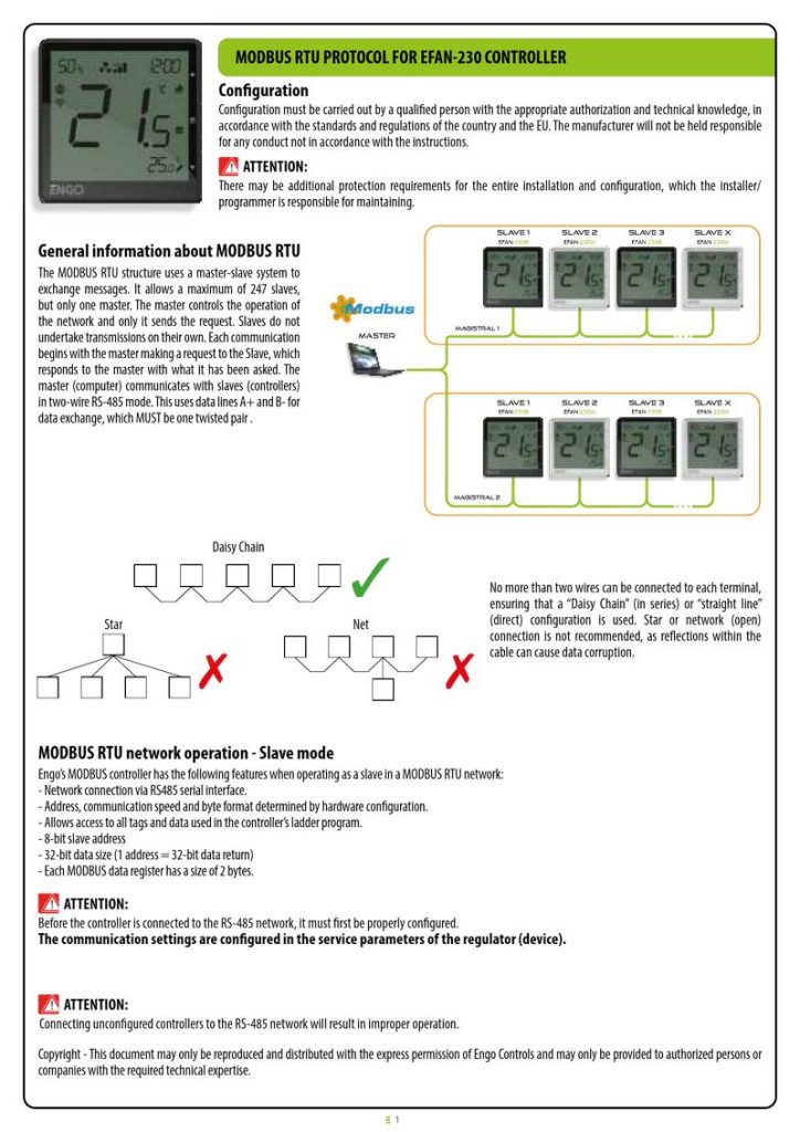
General information about MODBUS RTU
The MODBUS RTU structure uses a master-slave system to
exchange messages. It allows a maximum of 247 slaves,
but only one master. The master controls the operation of
the network and only it sends the request. Slaves do not
undertake transmissions on their own. Each communication
begins with the master making a request to the Slave, which
responds to the master with what it has been asked. The
master (computer) communicates with slaves (controllers)
in two-wire RS-485 mode. This uses data lines A+ and B- for
data exchange, which MUST be one twisted pair .
Magistral 1
master
SLAVE 1
EFAN-230B
SLAVE 2
EFAN-230W
SLAVE 3
E-B
SLAVE X
EFAN-230W
Magistral 2
Daisy Chain
No more than two wires can be connected to each terminal,
ensuring that a “Daisy Chain” (in series) or “straight line”
(direct) configuration is used. Star or network (open)
connection is not recommended, as reflections within the
cable can cause data corruption.
Star
Net
MODBUS RTU network operation - Slave mode
Engo’s MODBUS controller has the following features when operating as a slave in a MODBUS RTU network:
- Network connection via RS485 serial interface.
- Address, communication speed and byte format determined by hardware configuration.
- Allows access to all tags and data used in the controller’s ladder program.
- 8-bit slave address
- 32-bit data size (1 address = 32-bit data return)
- Each MODBUS data register has a size of 2 bytes.
ATTENTION:
Before the controller is connected to the RS-485 network, it must first be properly configured.
The communication settings are configured in the service parameters of the regulator (device).
ATTENTION:
Connecting unconfigured controllers to the RS-485 network will result in improper operation.
Copyright - This document may only be reproduced and distributed with the express permission of Engo Controls and may only be provided to authorized persons or
companies with the required technical expertise.
1

| General | Details |
|---|---|
| Name | Engo EFAN-230 Zigbee Smart Thermostat Owner’s Manual |
| Make | ENGO |
| Language | English |
| Filetype | PDF (Download) |
| File size | 0.12 MB |


ENGO E55W230WIFI Wi-Fi Thermostat User Guide

ENGO E20i Series Wi-Fi Wireless Internet Thermostat User Guide

ENGO EONEBATW, EONEBATB Internet Controlled Thermostat User Guide

ENGO E901 Programmable Wired Thermostat User Manual

ENGO E901 Wireless Internet Thermostat User Manual

ENGO EASY230W Wired Thermostat User Guide

ENGO EASYBATB Wired Battery Thermostat User Guide
Engo EFAN-230 Zigbee Smart Thermostat Owner’s Manual Overview
Summary of Contents
- Page 1: MODBUS RTU protocol for EFAN-230 controller Configuration must be carried out by a qualified person with the appropriate authorization and technical knowledge. There may be additional protection requirements for the entire installation and configuration. The MODBUS RTU structure uses a master-slave system to exchange messages. It allows a maximum of 247 slaves, but only one master. The master controls the operation of the network and only it sends the request. Each communication begins with the master making a request to the Slave. The master communicates with slaves in two-wire RS-485 mode. No more than two wires can be connected to each terminal, ensuring a daisy chain or straight line configuration. Before the controller is connected to the RS-485 network, it must first be properly configured.
- Page 2: RS-485 communication settings MODBUS Slave device address (ID). Baud - Bitrate (Baud). Parity bit - sets data parity for error detection. Supports the following function codes: #03, #04, #06. INPUT registers - read only. Value of the Integrated temperature sensor, °C. Value of the External temperature sensor S1, °C. Value of the External temperature sensor S2, °C. Fan state. Humidity measurement (with 5% indication accuracy).
- Page 3: Holding registers – for reading and writing Engo MODBUS Model ID 1 = 2 pipe - only heating 2 = 2 pipe - only cooling 3 = 2 pipe - heating & cooling 4 = 2 pipe - underfloor heating 5 = 4 pipe - heating & cooling Input inactive. Change between heating and cooling with the buttons. Input used to change heating/cooling via external contact connected to S1-COM. The controller switches between heating and cooling modes based on the pipe temperature set in parameters P17 and P18. Allow fan operation dependent on the temperature measurement on the pipe.
- Page 4: Fan on temperature for heating The fan will start working if the temperature in the room drops below the preset by the value of the parameter. Control algorithm for the heating valve Installer parameters -P12. FAN delta algorithm for cooling The parameter determines the width of the temperature range in which the fan operates in cooling mode. Fan on temperature for cooling The fan will start working if the temperature in the room rises above the setpoint by the value of the parameter. Hysteresis value for the cooling valve Installer parameters -P15. Dead zone of switching heating/cooling The difference between the set temperature and room temperature, at which the controller will automatically change the heating/cooling operation mode. Switching temperature value from heating to cooling - 2-pipe system Below this value the system switches to cooling mode and allows the fan to start. Switching temperature from cooling into heating - 2-pipe system Above this value the system switches to heating mode and allows the fan to start. Cooling ON delay A parameter used in 4-pipe systems with automatic switching between heating and cooling. Maximum floor temperature Heating will be turned off when the floor sensor temperature rises above the maximum value.
- Page 5: Minimum floor temperature is set to protect the floor by activating heating when the sensor temperature drops below a specified value. Installer parameters include a PIN code for settings, with the first default code being 0000. A PIN code can be required to unlock the keys, with options for enabling or disabling this feature. Fan operation can be toggled on or off, with output contacts for fan control being completely disabled when inactive. Operation modes include manual, schedule, and frost (anti-freeze) mode. Fan speed settings range from off to automatic speeds across multiple gears. Display brightness can be adjusted from 0 to 100 percent. Clock settings include minutes, hours, and the day of the week, with specific ranges for each. Temperature settings can be configured for schedule mode, manual mode, and frost mode, with defined maximum and minimum setpoint temperatures. Correction of displayed temperature can be made in increments of 0.5°C, with options for selecting the system type as heating or cooling.

Honeywell Home DT4M Wired Room Thermostat User Manual

hansgrohe AXOR UNO2 Concealed Thermostat with Shut Off Valve Instruction Manual

EUROSTER 4040 Smart Programmable Thermostat User Manual

Danfoss RT 8L Thermostat Installation Guide

SALUS RT310i Internet Thermostat Installation Guide

aube technologies TH104PLUS Programmable Thermostat Owner’s Manual

elko One Matter Thermostat Owner’s Manual

tecnoswitch Raffaello 230 TE215VU Electronic Recessed Thermostat User Guide

meross MTS200HK Smart Wi-Fi Thermostat User Manual

GENERAL Life ARUNA 300S Wired Room Thermostat User Guide