
GREYSTONE TLFLF24X01 Flying Lead Low Limit Thermostat Instruction Manual
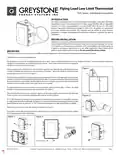


Flying Lead Low Limit Thermostat
TLFL Series - Installation Instructions
INTRODUCTION
The single point flying lead low limit thermostat incorporates a precision thermistor
temperature sensor and provides a Form C relay output (NO/NC) with an adjustable
setpoint. The sensor is encapsulated in a 6 mm (0.236”) OD X 50 mm (2”), 304 series
stainless steal probe. Standard wire length is 3.05m (10’). All probes are constructed
to provide excellent heat transfer, fast response and are potted to resist moisture
penetration. A hinged and gasketed Polycarbonate enclosure is provided for ease of
installation.
BEFORE INSTALLATION
Readtheseinstructionscarefullybeforeinstallingandcommissioningthetemperature
sensor. Failure to follow these instructions may result in product damage. Do not use
in an explosive or hazardous environment, with combustible or flammable gases, as
a safety or emergency stop device or in any other application where failure of the
product could result in personal injury. Do not exceed the device ratings.
MOUNTING
The flying lead sensor can be used in several different types of applications where single point temperature monitoring is required.
Listed below are some typical applications
The flying lead sensor can be installed directly into any air duct. Select a suitable installation area in the middle of the duct. To achieve the best reading, do
not place in an area where air stratification may be present. Avoid areas where the sensor is exposed to
vibrations or rapid temperature changes.
Figure 1
Once a suitable spot is selected, drill a 3/8”hole in the top of the duct and slide the probe through, mount
a length of flexible duct hanger from top to bottom of the duct. Mount the probe to the duct hanger
using a tube clamp or wire tie. See Figure 1.
The flying lead could also be used to measure pipe temperature. Select a suitable spot along the pipe,
remove a small section of insulation if present and set aside. It is recommended that thermal compound
be used to improve heat transfer. Spread a liberal amount on the pipe. Lay probe in thermal compound
and secure sensor to pipe using a worm gear clamp (not included).
For added protection it is recommended to wrap the probe cable around the pipe 1-2 times. Re-install
insulation if present, allowing sensor cable to protrude. See Figure 2.
The enclosure has a hinged cover with latch. Open cover by pulling slightly on the latch on the right side
of the enclosure. At the same time pulling on the cover, as shown in Figure 3.
Figure 2
A 1/2" NPT threated connection hole is provided in the bottom of the enclosure. Screw the EMT connector
or cable gland connector in until tight. See Figure 4. It is recommended that weatherproof conduit or cable
gland fittings be used. An optional 1/2" NPT to M16 thread adapter and cable gland fitting is available.
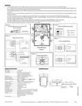
Make wiring connections as per the“Wiring”illustrations on Page 2.
Swing door closed until securely latched. For added security, 2 screws are provided that may be installed
in the integrated screw tabs. See Figure 5.
Figure 3
Figure 4
Figure 5
Thread adapter and
cable gland fitting
EMT Connector
Page 1
IN-GE-TLFLXXX-003
Copyright © Greystone Energy Systems, Inc. All Rights Reserved Phone: +1 506 853 3057 Web: www.greystoneenergy.com


| General | Details |
|---|---|
| Name | GREYSTONE TLFLF24X01 Flying Lead Low Limit Thermostat Instruction Manual |
| Make | Greystone |
| Language | English |
| Filetype | PDF (Download) |
| File size | 0.21 MB |
 (1 votes, average: 5.00 out of 5)
 Loading...

GREYSTONE TLGLF24X01 Glass Low Limit Thermostat Instruction Manual

GREYSTONE TLDF Series Flexible Cable Duct Average Low Limit Thermostat Instruction Manual

GREYSTONE TLOSF24X01 TLOS Series Outside Low Limit Thermostat Instruction Manual

GREYSTONE TLDCB24J01 Flexible Copper Duct Average Low Limit Thermostat Instruction Manual


TELLUR TLL331441 Thermostat Instructions

Schneider Electric TC-2931 Changeover Thermostat Instruction Manual

GENERAL LIFE MITRA 250 RF Digital Room Thermostat User Manual

SALUS CONTROLS IT800WIFI Smart Thermostat Installation Guide

telethings 2D Smart LoRaWAN Thermostat User Manual

Honeywell TH8321WF1001 Programmable Thermostat User Guide
Netmostat N-1 Smart Wifi Programmable Thermostat User Manual

Honeywell Home FocusPRO N100 Series Non Programmable Thermostat Installation Guide

Roth 1135006445 Wireless Room Thermostat Touchline 230 V Instruction Manual

Network Thermostat NetX X7 Series Thermostat Instruction Manual