Home > TECH CONTROLLERS > TECH CONTROLLERS EU-T-4.1n, EU-T-4.2n Wireless Thermostat User Manual
TECH CONTROLLERS EU-T-4.1n, EU-T-4.2n Wireless Thermostat User Manual


EU-T-4.1n
EU-T-4.2n

| General | Details |
|---|---|
| Name | TECH CONTROLLERS EU-T-4.1n, EU-T-4.2n Wireless Thermostat User Manual |
| Make | TECH CONTROLLERS |
| Language | English |
| Filetype | PDF (Download) |
| File size | 0.53 MB |


TECH CONTROLLERS EU-R-8b PLUS Wireless Two Position Room Thermostat User Manual

TECH CONTROLLERS EU-R-12b Wireless Room Thermostat User Manual

TECH CONTROLLERS EU-T-4.1n Wireless Thermostat User Manual

TECH CONTROLLERS EU-T-4.1n, EU-T-4.2n Wireless Thermostat User Manual Overview
Summary of Contents
- Page 1: Page 1
- Page 2: Safety Device description How to install the controller First start-up How to use the regulator Principle of operation Operation modes Main screen view and description Controller functions Technical data
- Page 3: USER MANUAL SAFETY Before using the device for the first time, the user should read the following regulations carefully. Not obeying the rules included in this manual may lead to personal injuries or controller damage. The user’s manual should be stored in a safe place for further reference. In order to avoid accidents and errors, it should be ensured that every person using the device has familiarized themselves with the principle of operation as well as security functions of the controller. The manufacturer does not accept responsibility for any injuries or damage resulting from negligence; therefore, users are obliged to take the necessary safety measures listed in this manual to protect their lives and property. WARNING A live electrical device! Make sure the regulator is disconnected from the mains before performing any activities involving the power supply. The device should be installed by a qualified electrician. The device should not be operated by children. The device may be damaged if struck by lightning. Make sure the plug is disconnected from the power supply during a thunderstorm. Any use other than specified by the manufacturer is forbidden. We are committed to protecting the environment. The user is obliged to transfer their used equipment to a collection point where all electric and electronic components will be recycled.
- Page 4: Device description The EU-T-4.1N/EU-T-4.2N room regulator is intended for controlling the heating device. Its main task is to maintain the pre-set temperature in the flat by sending a signal to the heating/cooling device. Advanced software enables the regulator to fulfil a wide range of functions. Maintaining the pre-set room temperature. Manual mode. Day/night program. Weekly control. Optimum Start. Heating/cooling. The controller should be installed by a qualified electrician.
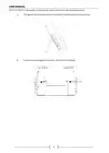
- Page 5: The EU-T-4.1N/EU-T-4.2N regulator may be put in any place or used as a wall-mountable panel. The regulator may be supported with a stand which should be attached to the back cover. In order to hang the regulator on the wall, remove the stand carefully.
- Page 6: In order to insert batteries, remove the back cover. The room regulator should be connected to the heating device or the CH boiler controller with the use of a two-core cable. If pump manufacturer requires an external main switch, power supply fuse or additional residual current device selective for distorted currents it is recommended not to connect pumps directly to pump control outputs. To avoid damaging to the device, an additional safety circuit must be used between the regulator and the pump. The manufacturer recommends the ZP-01 pump adapter, which must be purchased separately.
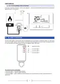
- Page 7: User manual Connection diagram In the case of wireless connection, use the above diagrams - a two-core communication cable should be connected to appropriate ports in the receiver. Receiver The EU-T-4.2N regulator communicates with the heating device by means of a radio signal sent to the EU-MW-3 receiver. Such a receiver is connected to the heating device by means of a two-core cable and communicates with the room regulator using a radio signal. The receiver has three control lights: Red control light 1 – it signals data reception. Red control light 2 – indicates receiver operation. Red control light 3 – goes on when the room temperature fails to reach the pre-set value; the heating device is switched on.
- Page 8: In case of no communication, the receiver automatically disables the heating device after 15 minutes. To register the EU-MW-3 receiver, press the registration button and select the Reg function in the Menu of the regulator. The message Scs indicates successful registration, while Err signifies a registration error. The number of registered relays is displayed on the screen, and if the maximum number is reached, you can choose to unregister them. To start the regulator for the first time, insert the batteries and connect the two-core cable to the appropriate sockets. The EU-T-4.1N/EU-T-4.2N room regulator maintains the pre-set room temperature by sending a signal to the heating device. The room regulator may operate in day/night mode, allowing different temperature settings for daytime and nighttime. Users can define the exact time for entering day mode and night mode. To activate day/night mode, press one of the buttons until the day/night mode icon appears on the main screen.
- Page 9: Weekly control allows users to define the timing for comfort and economical temperatures. Users can set 9 different programs divided into three groups: Programs 1-3 for daily settings, Programs 4-6 for weekdays and weekends, and Programs 7-9 for individual daily settings. The current weekly control program is displayed, showing hours for comfort and economical temperatures. To activate weekly control, press a button until the icon appears on the main screen. Manual mode allows for manual temperature adjustment using plus/minus buttons. Manual mode is activated automatically when a button is pressed and enters sleep mode until the next temperature change. Manual mode can be deactivated by pressing one of the buttons. In Day/night mode, pressing the plus/minus button activates manual mode. The controller returns to Day/night mode when daytime changes to nighttime or vice versa.
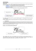
- Page 10: Example 2 - manual mode activation in weekly control mode When weekly control mode is active, the user changes the pre-set temperature by pressing plus/minus button (+ -), which automatically activates manual mode. The controller returns to weekly control mode when, according to the weekly schedule, daytime changes into nighttime or when the user presses one of the buttons. Main screen view and description The user operates the device using buttons. While one parameter is being edited, the remaining icons are not displayed. Display In the main screen view, use this button to activate weekly control mode. Minus button (-) – in the main screen view, press this button to switch to manual mode and decrease the pre-set temperature value. Menu – hold this button to enter the controller menu. Plus button (+) – in the main screen view, press this button to switch to manual mode and increase the pre-set temperature value. In the main screen view, use this button to activate day/night mode.
- Page 11: Day of the week An icon informing about current economical temperature. An icon informing about current comfort temperature. Pre-set room temperature. Time. Buttery level. An icon informing about room cooling/heating. Current operation mode: weekly, manual, day/night. Current room temperature. Parameter icons.
- Page 12: Parameter icons Clock settings Weekly control settings Comfort temperature Economical temperature Hysteresis Optimum start / heating/cooling mode selection Temperature sensor calibration The user navigates the menu structure using all the buttons Main menu includes day of the week, clock, and button lock
- Page 13: User manual Clock In order to set current time, enter the menu and press until time setting screen appears on the screen. By pressing + or - set the hour and minutes. Press to confirm and move on to the next parameter or press and hold MENU to confirm and return to the main screen view. Day This function enables the user to define the exact time of entering the day mode. When Day/night mode is active, comfort temperature applies at daytime. To configure this parameter press + or - set the hour and minute of day mode activation. Night This function enables the user to define the exact time of entering the night mode. When Day/night mode is active, economical temperature applies at nighttime. To configure this parameter press + or - set the hour and minute of night mode activation. Button lock In order to activate the button lock, press MENU until a padlock icon appears. Use one of the buttons to select ON. Optimum start Optimum start is an intelligent system controlling the heating/cooling process. It involves constant monitoring of the heating/cooling system efficiency and using the information to activate the heating/cooling process in advance. The system requires no user intervention.
- Page 14: Activating this function means that at the time of pre-programmed change of the pre-set temperature, the current room temperature is close to the desired value. In order to configure this parameter, press one of the buttons to access the setting panel. Use + or - to activate or deactivate the Optimum start function. This function enables manual mode control. If the function is disabled, the manual mode remains active regardless of the pre-programmed changes. This function is used to change the current weekly control program and edit the weekly programs. When weekly control is enabled, the current program is activated. Weekly program allows the user to define the time when comfort temperature and economical temperature will apply. If the user wants to edit programs 1÷3, there is no possibility of selecting particular days of the week. If the user wants to edit programs 4÷6, it is possible to edit the settings for weekdays and the weekend separately.
- Page 15: User manual If the user wants to edit programs 7÷9, it is possible to edit the settings for each day separately. In order to choose the days when a given program should apply, use of the Menu button. An hour which is being edited is displayed on the controller screen. To assign comfort temperature, press the plus button (+). To select economical temperature, press the minus button (-). The parameters of the weekly program are displayed at the bottom of the screen. When the user finishes the editing process by pressing the MENU button, the controller returns to the main screen view. Pre-set comfort temperature is used in weekly control mode and day/night mode. Pre-set economical temperature is used in weekly control mode and day/night mode. Room temperature hysteresis defines the tolerance of the pre-set temperature at which cooling or heating is activated. In order to set the hysteresis, press one of the buttons until the hysteresis settings appear on the screen.
- Page 16: Use + or - to set the desired hysteresis value. The room regulator reports that the temperature is too low only when the room temperature drops to 22 °C. Calibration setting range is from -10°C to +10°C with the accuracy of 0.1°C. To view the service menu, it is necessary to enter the code – 215. This function enables the user to select the room regulator operation mode: COOL or HEAT. This function enables the user to set the minimum (T1) and the maximum (T2) pre-set room temperature. Optimum start calibration starts when the controller detects the heating need to reach the pre-set temperature. This function enables the user to restore factory settings. Press MENU to confirm and return to the main screen view. Press EXIT to confirm and return to the main screen view.
- Page 17: Technical data Power supply: 2xAA, 1.5V batteries Room temperature adjustment range: 5°C ÷ 35°C Potential-free contact nominal output load: 230V AC / 0.5A (AC1) and 24V DC / 0.5A (DC1) Measurement error: ± 0.5 Operation frequency: 868MHz Maximum power consumption: <1W Operation temperature: 5°C ÷ 50°C Max. transmission power: 25mW AC1 load category: single-phase, resistive or slightly inductive AC load DC1 load category: direct current, resistive or slightly inductive load
- Page 18: EU declaration of conformity We declare under our sole responsibility that EU-T-4.1N manufactured by TECH STEROWNIKI II Sp. z o.o. is compliant with Directive 2014/35/EU on the harmonisation of the laws of Member States relating to the making available on the market of electrical equipment designed for use within certain voltage limits. Directive 2014/30/EU relates to electromagnetic compatibility. Directive 2009/125/EC establishes a framework for the setting of ecodesign requirements for energy-related products. The regulation by the Ministry of Entrepreneurship and Technology of 24 June 2019 concerns the essential requirements regarding the restriction of the use of certain hazardous substances in electrical and electronic equipment. For compliance assessment, harmonized standards were used: PN-EN IEC 60730-2-9:2019-06, PN-EN 60730-1:2016-10, EN IEC 63000:2018 RoHS. We declare under our sole responsibility that EU-T-4.2N manufactured by TECH STEROWNIKI II Sp. z o.o. is compliant with Directive 2014/53/EU on the harmonisation of the laws of the Member States relating to the making available on the market of radio equipment. For compliance assessment, harmonized standards were used: PN-EN IEC 60730-2-9:2019-06, PN-EN 62479:2011, ETSI EN 301 489-1 V2.2.3, ETSI EN 301 489-3 V2.1.1, ETSI EN 300 220-2 V3.2.1, ETSI EN 300 220-1 V3.1.1, EN IEC 63000:2018 RoHS. Wieprz, 22.08.2023
- Page 19: Page 19
- Page 20: Page 20

EMERSON 1F75H-21PR Programmable Heat Pump Thermostat Instruction Manual

GENERAL LIFE NORA 270S RF Digital Room Thermostat User Manual
Total Home TTHWD Wired Digital Room Thermostat User Guide

Robertshaw RS9320T Programmable Touchscreen Wall Thermostat Instruction Manual

ideal HEATING Halo Combi RF Wireless Boiler Thermostat User Guide

GENERAL 300S Wired Room Thermostat User Manual

Danfoss Heating Solutions WT-T BasicPlus2 Room Thermostat Installation Guide

Honeywell T3 Programmable Thermostat User Guide

ENGO CONTROLS E10-B Wi-Fi Thermostat User Guide

Ferono FTH-30 Universal Thermostat Instruction Manual