
Home > WHITE RODGERS > WHITE-RODGERS 1F86-444 Non Programmable Electronic Digital Thermostat Instruction Manual
WHITE-RODGERS 1F86-444 Non Programmable Electronic Digital Thermostat Instruction Manual
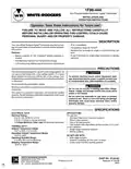
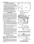
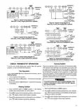
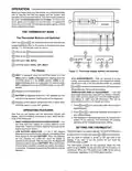


1F86-444
Non-Programmable Electronic Digital Thermostat
WHITE-RODGERS
INSTALLATION AND
OPERATION INSTRUCTIONS
Operator: Save these instructions for future use!
FAILURE TO READ AND FOLLOW ALL INSTRUCTIONS CAREFULLY
BEFORE INSTALLING OR OPERATING THIS CONTROL COULD CAUSE
PERSONAL INJURY AND/OR PROPERTY DAMAGE.
DESCRIPTION
Your new White-Rodgers Digital Thermostat uses the technol-
ogy of a solid-state microcomputer to provide precise tempera-
ture control.
• °F/°C convertibility
• Temperature range 45° to 90°F
• Standard five terminals for single or two-transformer sys-
tems
Features:
• Battery powered (3 “AA” Energizer® alkaline batteries in-
cluded).
• B and O terminals for single stage heat pumps or damper
operation
• Simultaneous heat and cool temperature storage
• LCD continuously displays set point and room temperature
PRECAUTIONS
Thisthermostatisintendedforusewithalowvoltagesystem;do
not use this thermostat with a line voltage system. If in doubt
about whether your wiring is millivolt, line, or low voltage, have
itinspectedbyaqualifiedheatingandairconditioningcontractor
or electrician.
CAUTION
!
To prevent electrical shock and/or equipment dam-
age, disconnectelectricpowertosystem, atmainfuse
or circuit breaker box, until installation is complete.
Do not exceed the specification ratings.
WARNING
!
Allwiringmustconformtolocalandnationalelectricalcodesand
ordinances.
Do not use on circuits exceeding specified voltage.
Higher voltage will damage control and could cause
shock or fire hazard.
This control is a precision instrument, and should be handled
carefully. Roughhandlingordistortingcomponentscouldcause
the control to malfunction.
Do not short out terminals on gas valve or primary
control to test. Short or incorrect wiring will damage
thermostat and could cause personal injury and/or
property damage.
SPECIFICATIONS
ELECTRICAL DATA
Electrical Rating:
APPLICATIONS
For use with:
8 to 30 VAC 50/60 Hz. or D.C.
0.05 to 1.5 Amps (Load per terminal)
1.5 Amps Maximum Total Load (All terminals combined)
•
•
•
•
Standard heat/cool or heat only systems
Electric heat systems
Gas or oil fired systems
Gas systems with intermittent ignition devices (I.I.D.) and/
THERMAL DATA
or vent dampers
Setpoint Temperature Range:
45°F to 90°F (7°C to 32°C)
Operating Ambient Temperature Range:
32°F to 105°F
Operating Humidity Range:
0 to 90% RH (non-condensing)
Shipping Temperature Range:
-40°F to 150°F
•
•
Single-stage heat pump systems
Millivolt systems
DO NOT USE WITH:
•
•
•
Multi-stage systems
Systems exceeding 30 VAC and 1.5 amps
3-wire zoned hydronic heating systems
WHITE-RODGERS DIVISION
EMERSON ELECTRIC CO.
9797 REAVIS ROAD
ST. LOUIS, MISSOURI 63123-5398
PART NO. 37-5410C
Replaces 37-5410B
9805
Printed in U.S.A.
R


| General | Details |
|---|---|
| Name | WHITE-RODGERS 1F86-444 Non Programmable Electronic Digital Thermostat Instruction Manual |
| Make | WHITE RODGERS |
| Language | English |
| Filetype | PDF (Download) |
| File size | 0.11 MB |
 (1 votes, average: 5.00 out of 5)
 Loading...

White-Rodgers 1E78 Non Programmable Heat Only Thermostat User Manual

White-Rodgers 1F97-1277 Big Blue Single Stage Thermostat User Manual

White-Rodgers 1F56N-444 Thermostat User Manual

White-Rodgers 1F83-277 Heating & Air Conditioning Auto Changeover Heat Pump Thermostat User Manual

White-Rodgers M30 Thermostat Instruction Manual

WHITE-RODGERS 1F51N-619 Low Voltage Evaporative Cooler Thermostat Instruction Manual

White Rodgers 1F78-151 Non Programmable Thermostat Instructions

WHITE RODGERS 1F80-51 Programmable Electronic Digital Thermostat Instruction Manual

WHITE-RODGERS 1F86-0471 Blue Single 1 1 Stage Thermostat Instruction Manual

WHITE-RODGERS 1F90-71 5-Day 2-Day Electronic Digital Thermostat Instruction Manual

White-Rodgers 1F86-444 Manual: Questions and Answers
How do I install batteries in my White-Rodgers 1F86-444?
The thermostat requires 3 AA alkaline batteries. Install them along the top of the base with positive ends facing left, then remove the battery tag to engage them.
- Position three AA Energizer alkaline batteries at the top of the base.
- Orient batteries with positive (+) ends to the left.
- Remove the battery tag to activate the batteries. Instruction Manual, p. 2
Where is the electric heat switch located on White-Rodgers 1F86-444?
On the back of the thermostat base, shown in Figure 1 of the manual. Instruction Manual, p. 2
What is the temperature range for White-Rodgers 1F86-444?
45°F to 90°F (or 7°C to 32°C). Instruction Manual, p. 1
Can I use White-Rodgers 1F86-444 with multi-stage heating and cooling systems?
No. The thermostat is not designed for multi-stage systems, systems exceeding 30 VAC and 1.5 amps, or 3-wire zoned hydronic heating systems. Instruction Manual, p. 1
More White-Rodgers thermostat manuals

CENTER EHE0200123 Wired 7 Day Programmable Thermostat Installation Guide

hansgrohe Ecostat 1001 SL Shower Thermostat Instruction Manual

Comfortmaker TSTATIIEWF-01 Ion Gray Smart Thermostat Owner’s Manual

Danfoss M30 React Radiator Thermostat Installation Guide

Google Cloud 2024 Nest Learning Thermostat Instructions

ENGO CONTROLS EASYBATB Wired Thermostat User Guide

SALUS WQ610RF Wireless Slim Programmable Thermostat Installation Guide

TIOEVO0003 TEVO Wireless Thermostat User Manual

Danfoss RET1000 Floor Heating Room Thermostat Installation Guide

hager TX320 Room Thermostat User Manual