
Home > WHITE RODGERS > WHITE-RODGERS 1F86-444 Non Programmable Electronic Digital Thermostat Instruction Manual
WHITE-RODGERS 1F86-444 Non Programmable Electronic Digital Thermostat Instruction Manual


INSTALLATION
REMOVE OLD THERMOSTAT
1. Shut off electricity at the main fuse box until installation is
complete. Ensure that electrical power is disconnected.
2. Remove the front cover of the old thermostat. With wires
still attached, remove wall plate from the wall. If the old
thermostathasawallmountingplate,removethethermostat
and the wall mounting plate as an assembly.
3. Identify each wire attached to the old thermostat using
the labels enclosed with the new thermostat.
ELECTRIC
GAS
4. Disconnect the wires from old thermostat one at a time. DO
NOT LET WIRES FALL BACK INTO THE WALL.
5. Install new thermostat using the following procedures.
Electric/Gas switch
ELECTRIC HEAT OR SINGLE-STAGE HEAT
PUMP SYSTEMS
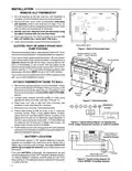
Figure 1. Back of thermostat base
Read entire paragraph before setting electric heat switch. If you
areunsureofyourapplication,contactaqualifiedserviceperson.
Alkaline batteries (3 "AA"–
install "+" ends to the left)
If you have a single-stage heat pump system, OR your system
uses central electric heat, where the blower is energized by a
separate circuit through the fan relay (meaning that the fan
turns on immediately on call for heat), then the switch on the
back of the thermostat base must be moved to the “ELECTRIC”
position (see fig. 1). If the thermostat is energizing electric heat
sequencers, the switch MUST remain in the “GAS” position.
Screw anchors
RH
W
If you must move the switch to the “ELECTRIC” position (to the
left), use a small screwdriver or pencil.
RC
B
G
Y
O
ATTACH THERMOSTAT BASE TO WALL
1. Remove the packing material from the thermostat. Gently
pull the cover straight off the base. Forcing or prying on the
thermostatwillcausedamagetotheunit. Ifnecessary, move
the electric heat switch (see ELECTRIC HEAT SYSTEMS,
above).
Mounting
holes
2. Connect wires beneath terminal screws on base using
appropriate wiring schematic (see figs. 3 through 10).
Figure 2. Thermostat base
3. Place base over hole in wall and mark mounting hole
locations on wall using base as a template.
THERMOSTAT
SYSTEM
Y
B
O
G
W
RC
RH
4. Move base out of the way. Drill mounting holes.
5. Fasten base loosely to wall, as shown in fig. 2, using two
mounting screws. Place a level against bottom of base,
adjust until level, and then tighten screws. (Leveling is for
appearance only and will not affect thermostat operation.) If
you are using existing mounting holes, or if holes drilled are
too large and do not allow you to tighten base snugly, use
plastic screw anchors to secure subbase.
Heating
System
24 VAC Transformer
or
Thermopile
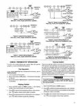
Figure 3. Typical wiring diagram for heating only,
2-wire, single transformer systems or millivolt systems
6. Push excess wire into wall and plug hole with a fire-resistant
material(suchasfiberglassinsulation)topreventdraftsfrom
affecting thermostat operation.
Thermostat
NOTE
3-wire Series 10
Primary Control
(located at furnace)
Jumper wire must be
added between R and B
terminals on the primary
control (jumper wire not
provided with thermostat).
BATTERY LOCATION
R
W
This thermostat requires 3 “AA” alkaline batteries to operate.
Batteries are installed in the thermostat at the factory with a
battery tag to prevent power drainage. You must remove the
battery tag to engage the batteries and provide power to the
thermostat.
B
W
R
If the word BATTERY is displayed, the batteries are low and
shouldbereplacedwithfresh“AA”Energizer® alkalinebatteries.
To replace batteries, install the batteries along the top of the
base(seefig.2).Thebatteriesmustbeinstalledwiththepositive
(+) ends to the left.
Furnace
Add jumper wire
(not provided with thermostat)
Figure 4. Typical wiring diagram for
3-wire SERIES 10 heating systems
2

| General | Details |
|---|---|
| Name | WHITE-RODGERS 1F86-444 Non Programmable Electronic Digital Thermostat Instruction Manual |
| Make | WHITE RODGERS |
| Language | English |
| Filetype | PDF (Download) |
| File size | 0.11 MB |
 (1 votes, average: 5.00 out of 5)
 Loading...

White-Rodgers 1E78 Non Programmable Heat Only Thermostat User Manual

White-Rodgers 1F97-1277 Big Blue Single Stage Thermostat User Manual

White-Rodgers 1F56N-444 Thermostat User Manual

White-Rodgers 1F83-277 Heating & Air Conditioning Auto Changeover Heat Pump Thermostat User Manual

White-Rodgers M30 Thermostat Instruction Manual

WHITE-RODGERS 1F51N-619 Low Voltage Evaporative Cooler Thermostat Instruction Manual

WHITE-RODGERS 1F90-71 5-Day 2-Day Electronic Digital Thermostat Instruction Manual

WHITE-RODGERS 1F95-1277 Universal Thermostat Owner’s Manual

White Rodgers 1F78-151 Non Programmable Thermostat Instructions

WHITE RODGERS 1F80-51 Programmable Electronic Digital Thermostat Instruction Manual

DAIKIN SQNSQ22 One Touch Smart Thermostat User Manual

Goldair GEPH213 EcoPanel Heater with Thermostat Instruction Manual

HITACHI ATW-RTU-11 Compact Wired Thermostat User Manual

micro-air EasyTouch 357 Multi Zone Replacement Thermostat Instruction Manual

SALUS Thermostat Sensor TS600 User Guide

Danfoss Link Connect Thermostat User Guide

VILPE WIVE 100 Intake Vent Plus Thermostat Installation Guide

Danfoss ECtemp 532 Electronic Thermostat Installation Guide

InfraComfort HY01WE Programmable Non Wi-Fi Thermostat User Manual

Day and Night TSTATIIEWF-01 Gray Smart Thermostat Owner’s Manual