
Home > CLIMATE MASTER > CLIMATE MASTER CXM2 Communicating Awc Thermostat Installation Guide
CLIMATE MASTER CXM2 Communicating Awc Thermostat Installation Guide


iGATE 2 COMMUNICATING (AWC) THERMOSTAT – IOM
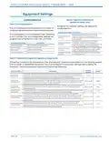
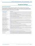
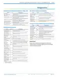
Equipment Settings
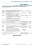
Table 11: Loop Configuration
Configures the internal vFlow device to the application. The vFlow device will adjust the flow to maintain
the selected temperature difference (ΔT) between the entering and leaving water for the active operating
mode. Loop configuration mode is only applicable to those system who have vFlow components installed
in them. The vFlow option is not available on all product lines and is offered as an option on certain product
lines. Please reference the unit model number located on the unit data plate with the model nomenclature
decoder in the unit IOM to determine if your product contains vFlow components.
System Setting
Description
Range/Options
Default
Single system
(one unit, one loop),
Parallel system
Single
system
Loop Option
Configures the application for the loop.
(multiple units,
one common loop,
parallel pumping)
Sets the source water flow rate for the heating mode. The variable
speed pump or modulating water valve will adjust the source water
flow to maintain the selected temperature difference between the
entering and leaving source water during the heating mode.
Sets the source water flow rate for the cooling mode. The variable
speed pump or modulating water valve will adjust the source water
flow to maintain the selected temperature difference between the
entering and leaving source water during the cooling mode.
Heating ΔT
Cooling ΔT
5.0°F to 12.0°F
9.0°F to 20.0°F
6.0°F
10.0°F
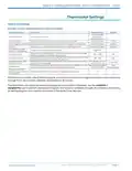
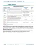
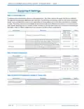
Table 12: Option Configuration
System Setting
Description
Range/Options
Default
Compressor ASCD (Anti-Short
Cycle Delay Time)
Configures the minimum amount of time the compressor will remain
off between cycles.
3 to 8 minutes1
5 minutes
Extended Compressor Operation Configures the control to monitor the compressor operation.
Enabled, Disabled
No (30°F), Yes (10°F)
Off, On
Enabled
No (30°F)
Off
LT1 (JW3) Jumper
Motorized Valve
Status of the JW3 jumper low temperature (antifreeze) operation.
Configures the compressor start delay until the valve is fully open.
Over/Under Voltage Detection
(applies to Tranquility)2
Configures the over/under voltage detection.
Enabled, Disabled
No - 30°F, Yes - 10°F
Enabled
No - 30°F
Configures the low temperature protection setting for the source
water heat exchanger.
Source Antifreeze
1. Range depends on the model of equipment.
2. Over/Under Voltage condition exists when the control voltage is outside the range of 18VAC to 31.5VAC.
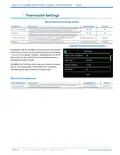
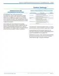
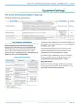
Table 13: DHW Pump Configuration (applies to Trilogy units)
System Setting
Description
Range/Options
Default
Configures the potable water flow rate for the water heating mode.
The variable speed potable water pump will adjust the potable water
flow to maintain the selected temperature difference between the
entering and leaving potable water during the water heating mode.
Water Heating ΔT (applies to
SmartTank Water Heater)
8.0°F to 12.0°F
8.0°F
PAG E : 1 4
Part#: 97B0132N01 | Revised: Februar y 06, 2025
w w w. c l i m a te m a s te r. c o m

| General | Details |
|---|---|
| Name | CLIMATE MASTER CXM2 Communicating Awc Thermostat Installation Guide |
| Make | CLIMATE MASTER |
| Language | English |
| Filetype | PDF (Download) |
| File size | 1.03 MB |
 (1 votes, average: 5.00 out of 5)
 Loading...


TELUS ASSORTED Smart Thermostat User Manual

Honeywell Home CT50 Series Thermostat Owner’s Manual

hyco PT01 Programmable Thermostat Instruction Manual

vtech T961NN50 E-Smart Thermostat Installation Guide

WILLIAMS P322016 Millivolt Wall Thermostat Instructions

Roth VVS-nr. 466397.058 Softline Standard Room Thermostat Instruction Manual

Mi-HEAT M2 Wi-fi Bluetooth Thermostat Instruction Manual

EAE Technology EAE-KNX MONA Series Thermostat Instruction Manual

hansgrohe AXOR STARCK Concealed Thermostat with Shut Off Valve Instruction Manual

Drayton RF710 Digital Wireless Room Thermostat Installation Guide