
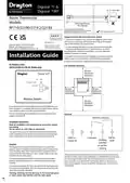
Drayton RF710 Digital Wireless Room Thermostat Installation Guide



+
Digistat 1 &
30cm Min
+
Digistat 1RF
BOILER
Room Thermostat
Models:
SCR
Radio Signal Range:
30m Typically
RF710/22190/2219
The range may be affected by
composition/density and number of walls
between the Digistat +RF and SCR
Preferred side of boiler
1. Loosen the securing screws, remove the wallplate, and if surface
wiring is to be used, snap out the cable entry strip on the bottom
edge of the wallplate with a pair of pliers.
06515065001 ISS G
Drayton Controls reserve the right
to make changes without notice
and cannot accept liability for errors.
2. Fix the wallplate, terminals at the top, either direct onto the flat
wall using wall plugs and no 6 x1” wood screws or on a flush
mounting single conduit box using M3.5 x 14 screws. Minimum
wallplate clearances are shown.
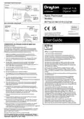
3. Complete the wiring to the SCR wallplate in accordance with the
relevant diagram, to comply with current IEE wiring regulations.
4. Place the SCR onto the wallplate and tighten the securing screws.
50 mm
minimum
clearance
Digistat SCR
On
N
L
1
2
3
4
Receive / Alarm
2
Override
Learn
Mode
1
40 mm
minimum
clearance
40 mm
minimum
clearance
Wireless System
70 mm
minimum
clearance
If you do not have the knowledge to install the SCR safely then you
must arrange for a competent electrician to install it for you. Wiring
must conform to the current IEE wiring regulations.
Prior to commencing the installation you must ensure the mains
supply is switched off.
Volt free contacts
N
L
1
2
3
The system wiring must be able to be fully disconnected from the
mains supply by a switch incorporated in the fixed wiring having a
contact separation of at least 3mm on both poles. Fused at 3A.
Call for
heat
230V a.c.
Fused 3A
Common
Heating
satisfied
or call for
cooling
The Digistat SCR (receiver) should be mounted in a convenient
position, close to the boiler or central heating system wiring centre.
(Care should be taken not to mount the SCR in a position where it
is surrounded by metal objects or mains voltage cable, as this may
interfere with the radio signal).
This product is double insulated and does not require an earth connection.
The SCR should be wired to the combi boiler or central heating wiring using
the correct type of cable or flex. The SCR should be wired in to replace
hard wired room or programmable thermostats shown on the system or
boiler wiring diagrams. Always check other manufacturers instructions for
compatibility.
For the best performance install in an open space, at least 30cm
distance from any metal objects including wall boxes and boiler
housing.
It is recommended that the SCR is mounted on the wall nearest the
final location of the Digistat +RF room thermostat and not less than
30cm from the boiler side panel.


| General | Details |
|---|---|
| Name | Drayton RF710 Digital Wireless Room Thermostat Installation Guide |
| Make | Drayton |
| Language | English |
| Filetype | PDF (Download) |
| File size | 1.06 MB |
 (1 votes, average: 5.00 out of 5)
 Loading...

Drayton RF902 Digistat 3rd Generation Wireless 2-Channel Programmable Thermostat Installation Guide

Drayton Wiser Smart Room Thermostat Instruction Manual

Drayton 2290M Digistat 3rd Generation Programmable Room Thermostat Installation Guide
Drayton 22902 Programmable 2 Channel Room Thermostat Installation Guide

Drayton 2290M Mains Digital Room Thermostat User Manual

Drayton RF710 Manual: Questions and Answers
What do the LED lights mean on the Drayton RF710?
Green LED indicates heating demand; red LED flashes every 5 minutes for 7 seconds when receiving radio signals. Installation Guide, p. 5
Can I use the Drayton RF710 with an oil boiler?
Yes. The Application Type setting supports Gas Boiler, Oil Boiler, and Electric Heat (relay model only). Installation Guide, p. 6
What's the difference between Fast and Slow system capability on the Drayton RF710?
Fast reaches setpoint in under 1 hour; Slow reaches setpoint in over 1 hour.
| Setting | Behavior |
|---|---|
| Fast | House usually reaches setpoint in < 1 hour |
| Slow | House usually reaches setpoint in > 1 hour |
How do I test the radio signal strength on the Drayton RF710?
Remove the batteries, press and hold the '+' button whilst refitting them. Display shows 'rF'. Return to the SCR receiver and check if the red LED continuously flashes, indicating good signal. Installation Guide, p. 5
More Drayton thermostat manuals

Honeywell TH9320WF Smart Thermostat 9000 Color Touchscreen Installation Guide

ideal HEATING HALO LITE Room Thermostat User Guide

LENNOX EL18KCV Smart Wi-Fi Communicating Thermostat User Manual

Glow-Worm SRT 50-2 Climastat Select Programmable Room Thermostat User Manual

EMOS P5601UF Floor Heating Thermostat User Manual

Network Thermostat X7-Series Thermostat Installation Guide

EBERLE UTE 1032-55, UTE 1032-50 Flush Mounted Room Thermostat Owner’s Manual

GENERAL FH100 Floor Heating Thermostat User Guide

LoRaWAN MC-LW-FCT-01 MClimate Fan Coil Thermostat User Manual

International Environmental GoldringFan Coil Digital Thermostat Installation Guide