Home > CLIMATE MASTER > CLIMATE MASTER CXM2 Communicating Awc Thermostat Installation Guide

CLIMATE MASTER CXM2 Communicating Awc Thermostat Installation Guide
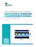
iGATE® 2 COMMUNICATING AWC THERMOSTAT  
INSTALLATION, OPERATION  
& MAINTENANCE MANUAL  
Part#: 97B0132N01 | Revised: February 06, 2025  
For use with CXM2 and DXM2.5 Controls  
AWC99U01  
GeneralDetails
NameCLIMATE MASTER CXM2 Communicating Awc Thermostat Installation Guide
MakeCLIMATE MASTER
LanguageEnglish
FiletypePDF (Download)
File size1.03 MB
Download PDF
1 Star2 Stars3 Stars4 Stars5 Stars (1 votes, average: 5.00 out of 5)
Loading...

CLIMATE MASTER CXM2 Communicating Awc Thermostat Installation Guide
Get the free PDF manual for the CLIMATE MASTER CXM2 Communicating Awc Thermostat Installation Guide and access setup steps, usage instructions, and troubleshooting tips. 👉 View online or download now to keep your thermostat running smoothly!
CLIMATE MASTER CXM2 Communicating Awc Thermostat Installation Guide Overview
Summary of Contents

  • Page 1: iGATE® 2 communicating AWC thermostat Installation, operation & maintenance manual For use with CXM2 and DXM2.5 controls
  • Page 2: Getting started Equipment settings Configuration Technical support Before you begin Specifications Unit manual operation Diagnostics Wiring requirements Operating information
  • Page 3: iGATE 2 communicating (AWC) thermostat – IOM These instructions are intended to be used by the installer or service personnel. End users are NOT advised to change or modify any of these settings. Doing so may cause the equipment to stop working properly and/or may void the warranty on both the thermostat and the equipment. The AWC thermostat is designed to be mounted on the homeowner’s wall in a convenient location. This product is intended to be installed by trained service professionals. This manual explains the procedures for installing the ClimateMaster iGate® 2 communicating (AWC) thermostat. Please read it carefully before beginning the installation. Wi-Fi connectivity supports Wi-Fi: 802.11 a/b/g/n standards on 2.4 GHz networks. Environmental operating range: 32° to 104°F (0° to 40°C), 10 to 95% relative humidity, non-condensing. Listed by FCC Part 15, Subpart J compliant. For information on how to operate the AWC thermostat, please see the iGate 2 user manual.
  • Page 4: iGATE 2 communicating (AWC) thermostat – IOM Installation considerations The thermostat requires no batteries and must have both R and C terminals connected. Before disconnecting any wires, take a photo of the current wire configuration. Mercury notice: This product does not contain mercury. Thermostat should be mounted approximately 5 ft. above floor and close to or in a frequently used room. Thermostat should not be mounted close to a window, on an outside wall, or next to a door leading to the outside. Wrap the wires around a pen or pencil to keep them from falling inside the wall. Disconnect electric power to the HVAC system before installing this product. All wiring must conform to your local electrical code. Use a level to ensure thermostat is properly aligned.
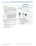
  • Page 5: iGATE 2 communicating (AWC) thermostat – IOM Installation Connect wires. Match your wire configuration to the terminals on the base. Reference Diagram 1. All excess wire should be pushed back into the wall as far as possible. Connect each wire individually by pushing down on the quick connect tab, inserting the wire into the connector opening, and then releasing the tab. If remote indoor and/or outdoor sensors are used, they may be connected at this time. Use pliers to straighten wire before inserting into new base. Be sure to cut any excess wire so that the insulation extends to the terminal block. When the wire is installed properly to the terminal block, there should be no copper exposed. 22 AWG shielded wire is required when installing a remote sensor further than 100 feet (30.5 meters). Attach the thermostat face.
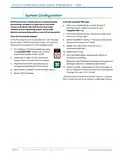
  • Page 6: iGATE 2 communicating (AWC) thermostat – IOM System configuration Ensure your mobile device is updated before proceeding. myUplink is supported on the latest version of Android, iOS, and the last two major versions of each operating system. With your mobile device within 15 feet of the thermostat, open then login to your myUplink PRO app. From the Systems screen, select the green ADD button at the top right. If the thermostat is not connected to a Wi-Fi router, skip to step 6. Select CONNECT LOCALLY. The app will find any devices in Access Point mode. Select the thermostat from the list of discovered devices. To configure the System Settings using the myUplink PRO mobile app, set the thermostat System Mode to OFF. When finished, cycle power to the thermostat to return to Station mode connecting to the internet through the user’s Wi-Fi router.
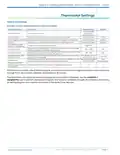
  • Page 7: Thermostat settings are available remotely and at the thermostat display. The thermostat name can be configured with a 16 character text input. Touch volume can be set to off, click, or beep, with the default being click. Auto daylight savings time can be enabled or disabled. Security requires a 4-digit PIN for access, with a range from 0000 to 9999. Active backlight intensity can be adjusted from 0% to 100%. Standby backlight intensity can be adjusted from 0% to 25%. The active to standby timer can be set between 5 to 30 seconds. The thermostat supports programmable and non-programmable operation for scheduling. With security enabled, notifications are sent after failed access attempts.
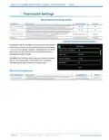
  • Page 8: Thermostat settings include advanced options for user configuration. Sync time and date with the cloud server based on thermostat location. Proximity sensing changes screen backlighting from standby to active when a person is detected. Increasing proximity sensitivity enhances detection range but may lead to false presence alerts. Wi-Fi functionality is essential for features like syncing time, outdoor temperature, and remote access. Disabling Wi-Fi requires re-setup using the mobile app. Alerts can be configured to indicate when it's time to clean or replace the air filter. The air filter reminder is set to 3,000 hours by default. The document includes tables for advanced settings and alert configuration. The page is part of the user manual for the iGATE 2 communicating thermostat.
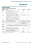
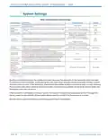
  • Page 9: iGATE 2 communicating (AWC) thermostat – IOM System settings Reference the system configuration section for information on accessing system settings. Available remotely (web/mobile) and at thermostat display. Auto mode allows automatic switching from heating to cooling to maintain the temperature between the setpoints. Adjust the staging option using the up/down arrow buttons for single stage or multi-stage compressor applications. Temperature control logic includes Proportional Integral and Proportional Integral (No Down Staging) options. Adjust the maximum number of on/off cycles per hour to maintain the desired indoor temperature. Configure the time zone of the thermostat. Configure the auxiliary heat mode for residential applications. Select how long the thermostat will hold the new temperature before reverting to the regular program. Configure the temperature scale to Fahrenheit or Celsius.
  • Page 10: iGATE 2 communicating (AWC) thermostat – IOM System settings Configures the operational timers within the thermostat to ensure timing accuracy. Indoor temperature offset allows for calibration of the temperature sensor by the selected amount. Humidity offset allows for calibration of the humidity sensor by the selected amount. Maximum heat setpoint available on the heat setpoint wheel is 88°F (31°C). Minimum cool setpoint available on the cool setpoint wheel is 65°F (18.5°C). Configures the sensitivity of the thermostat to the space temperature. Configures the amount of space temperature delta from set point allowed from the heating setpoint at maximum unit capacity. Occupancy input requires remote sensor set to occupancy and programming enabled. Thermostat serial number. Starting a temporary hold in the middle of a smart recovery uses the setpoints of the temporary hold.
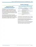
  • Page 11: iGATE 2 communicating (AWC) thermostat – IOM System settings Humidification and dehumidification settings Enables access point mode for local connection to the thermostat via the myUplink PRO mobile application. Provides a means to reset all thermostat settings back to their factory defaults. Humidification logic will communicate output when the space humidity is less than the setpoint. Dehumidification logic will reduce the cooling airflow when the space humidity is greater than the setpoint. The thermostat will automatically timeout of Access Point mode and return to Station mode after 2 hours. Disconnecting the Wi-Fi requires setting up the thermostat using the myUplink mobile application. Disabling this function after the thermostat has been set up and connected to the local Wi-Fi network requires setup again using the mobile app.
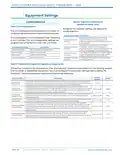
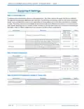
  • Page 12: iGATE 2 communicating (AWC) thermostat – IOM Equipment settings The Unit Configuration settings allow the installer to configure the thermostat to the installed equipment. Unit Configuration is only necessary when replacing a unit controller. Conforms the minimum unit heating capacity. Conforms the maximum unit heating capacity. Conforms the minimum unit cooling capacity. Conforms the maximum operational unit cooling capacity. This section configures the temperature, time, and capacity thresholds associated with the heating, cooling, and hot water equipment. You must configure the Equipment settings before setting the thresholds. Potable water heating normally takes priority over space heating. This setting establishes the maximum acceptable space temperature drop during the potable hot water mode before the unit switches to the space heating mode.
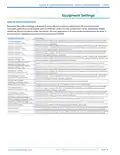
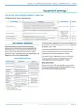
  • Page 13: iGATE 2 communicating (AWC) thermostat – IOM Equipment settings Range for the airflow settings will depend on model and capacity selection (in 25 cfm increments). Tranquility systems must be paired with CV ECM fan motors for this functionality to be applicable. Configuration setting Constitutes the unit airflow while operating at minimum capacity in the heating mode. Constitutes the unit airflow while operating at maximum capacity in the heating mode. Constitutes the unit airflow while operating at minimum capacity in the cooling mode. Constitutes the unit airflow while operating at maximum capacity in the cooling mode. Constitutes the unit airflow during the auxiliary heat mode (if applicable). Constitutes the unit airflow during the emergency heat mode (if applicable). This setting determines whether (and how long) the blower will continue to operate after the compressor has cycled off at the end of each heating cycle.
  • Page 14: iGATE 2 communicating (AWC) thermostat – IOM Loop configuration adjusts the flow to maintain the selected temperature difference between entering and leaving water. Loop configuration mode is applicable only to systems with vFlow components. The vFlow option is not available on all product lines. The source water flow rate is set for both heating and cooling modes. Heating ΔT ranges from 5.0°F to 12.0°F, while cooling ΔT ranges from 9.0°F to 20.0°F. Compressor ASCD configures the minimum off time between cycles. Extended compressor operation monitors compressor activity. Over/under voltage detection applies to Tranquility systems. The potable water flow rate is configured for the water heating mode. Water heating ΔT ranges from 8.0°F to 12.0°F.
  • Page 15: iGATE 2 communicating (AWC) thermostat – IOM Equipment settings Smart tank configuration applies to Trilogy units. Configure the hot water mode settings. When hot water efficiency is enabled, the AWS backup electric elements will operate when the connected heat pump is locked out or cannot keep up with the household hot water demand. Hot water mode determines the heat source for your hot water. Hot water setpoint establishes the set point for your hot water. Manual operation mode allows the service technician to manually command operation for operating mode, thermostat outputs, blower speed, and pump speed or valve position. Clear fault history will clear all fault codes stored in the thermostat as well as the fault history in any connected communicating controls. Selects the manual mode of operation. Sets loop pump speed and DHW pump speed.
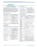
  • Page 16: iGATE 2 communicating (AWC) thermostat – IOM Diagnostics Blower diagnostics The diagnostics data set allows the service technician to view the real-time status of all physical inputs, switches, temperature sensor readings, as well as the operational status of the heat pump from the myUplink mobile app and web portal. Current temperature of the air entering the unit. Current temperature of the air leaving the unit. Compressor diagnostics Current compressor amperage. Current power consumption of the compressor. Current temperature of the refrigerant liquid line between the air coil and the electronic expansion valve. Current operating capacity as a percentage of the max capacity. Current calculation of superheat temperature at the discharge of the compressor. Loop diagnostics Current temperature of the water entering the source heat exchanger. Current temperature of the water leaving the source heat exchanger. Current feedback signal of the loop pump.
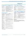
  • Page 17: iGATE 2 communicating (AWC) thermostat – IOM Diagnostics Refrigerant valve diagnostics (applies to Trilogy units) Hot water diagnostics (if available) Status of the RV1 (potable water heating) reversing valve. Control voltage of the hot water tank. Status of the hot water element relays. Status of the RV2 (heat/cool) reversing valve. Current temperature at the upper element of the storage tank. Current temperature at the lower element of the storage tank. Fault history stores and displays the five most recent fault or warning codes for the connected communicating control.
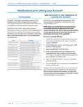
  • Page 18: iGATE 2 communicating (AWC) thermostat – IOM Notifications and linking your account The AWC thermostat can generate alerts if the temperature in the home goes over or under a pre-programmed level. This protects the home from damage due to freezing and/or excessive heat. To ensure an ongoing service relationship with your customer, link the AWC thermostat to your myUplink PRO portal. Alert/fault information, along with optional technician contact information will be displayed on the thermostat display. If the homeowner registers the thermostat, the alert will be emailed, notification sent in the mobile application, and be displayed in the web portal. Linking a device requires the device to be linked to the user’s myUplink account. myUplink PRO account holder will be charged a monthly fee for each thermostat linked to their account.
  • Page 19: iGATE 2 communicating (AWC) thermostat – IOM Part#: 97B0132N01 Revised: February 06, 2025
  • Page 20: iGATE 2 communicating (AWC) thermostat – IOM Revision history Updated formatting and visual style. Added samples of mentioned on-screen buttons. Updated sample thermostat settings screen. Updated temperature ranges for indoor temperature offset, max. heat setpoint, and min. cool setpoint. Clarified capabilities of different scheduling tools. Corrected dimension specifications. Clarified operating system support for mobile devices. Added configuration settings and diagnostic data for tranquility units. Created updated settings and configuration tables.