Home > Robertshaw > Robertshaw RS9423T Thermostat Installation Guide
Robertshaw RS9423T Thermostat Installation Guide

RS9423T
Installation Manual

| General | Details |
|---|---|
| Name | Robertshaw RS9423T Thermostat Installation Guide |
| Make | Robertshaw |
| Language | English |
| Filetype | PDF (Download) |
| File size | 1.03 MB |


Robertshaw RS9220 Programmable Thermostat Installation Guide

Robertshaw RS10420T WIFI Programmable Thermostat User Guide

Robertshaw RS8110 Non Programmable Thermostat Instruction Manual
Robertshaw RS8210 Thermostat Installation Guide

Robertshaw RS8210 Non-Programmable Multi-Stage 2H-1C Wall Thermostat User Manual

Robertshaw RS9220 Digital Programmable Wall Thermostat Instruction Manual

Robertshaw 9602 Programmable Thermostat User Manual

Robertshaw RS9320T Programmable Touchscreen Wall Thermostat Instruction Manual

Robertshaw RTC500 WIFI Thermostat Instruction Manual

Robertshaw RS1110 Programmable 1 Heat 1 Cool Wall Thermostat Instruction Manual

Robertshaw RS9423T Thermostat Installation Guide Overview
Summary of Contents
- Page 1: Page 1
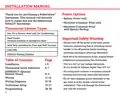
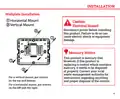
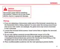
- Page 2: Installation manual for the Robertshaw RS9423T thermostat. Power options include battery power only, hardwire only, and hardwire with battery backup. Thermostat system types include gas, oil, or electric heat with air conditioning, heat pumps, heat only, cool only, and millivolt heating systems. Important safety warning: Always turn off the power at the main power source before installing, removing, cleaning, or servicing the thermostat. This is a 24V AC low voltage thermostat; do not install on voltages higher than 30V AC. All wiring must conform to local and national building and electrical codes and ordinances. Do not short across terminals on the gas valve or at the system control to test installation, as this will damage the thermostat and void the warranty. Read all information in this manual before installing or programming the thermostat. Table of contents includes installation, thermostat quick reference, wiring, wiring diagrams, technician setup, and programming.
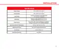
- Page 3: Installation Specifications Display range Control range Load rating Differential Power source Operating ambient temperature Operating humidity Dimensions
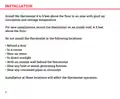
- Page 4: Install the thermostat 4 to 5 feet above the floor in an area with good air circulation and average temperature. For new installations, mount the thermostat on an inside wall, 4-5 feet above the floor. Do not install the thermostat behind a door. Do not install the thermostat in a corner. Do not install the thermostat near air vents. Do not install the thermostat in direct sunlight. Do not install the thermostat with an outside wall behind it. Do not install the thermostat near any heat or steam generating fixtures. Do not install the thermostat near any concealed pipes or chimneys. Installation at these locations will affect the thermostat operation.
- Page 5: Installation instructions are provided for wallplate installation. A caution regarding electrical hazards emphasizes the importance of disconnecting power before installation to avoid electric shock or equipment damage. The product is mercury-free, but if replacing a control that contains mercury, it must be disposed of properly. Contact local waste management authorities for recycling and disposal instructions. For vertical mounting, screws should be placed on the top and bottom. For horizontal mounting, screws should be placed on the left and right.
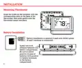
- Page 6: Installation Mounting thermostat involves aligning the tabs on the faceplate with the slots on the back of the thermostat and pushing gently until it snaps into place. Battery installation is optional if used with 24 VAC power. Install two AAA alkaline batteries into the battery compartment. Ensure to match positive ends of batteries with positive battery terminals in the battery compartment.
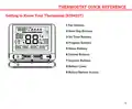
- Page 7: Thermostat quick reference Getting to know your thermostat (RS9423T) Fan buttons Next step buttons Set time buttons Program buttons Menu buttons System buttons Setpoint buttons Battery cover Button/battery access
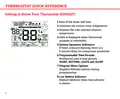
- Page 8: Thermostat quick reference Getting to know your thermostat (RS9423T) Indicates the current room temperature Displays the user selected setpoint temperature Hold is displayed when thermostat program is overridden System operation indicators: If these icons are flashing, there is a 5-minute delay for compressor protection Programmable time periods: Residential uses 4 time periods - WAKE, RETURN, LEAVE and SLEEP Program menu options: Displays different options during programming Low battery indicator: Replace batteries when this indicator is shown
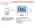
- Page 9: RS9055OUT optional remote sensor Outdoor sensor Durable weatherproof design The RS9055OUT is an optional wireless outdoor remote temperature sensor and can be used for dual fuel balance point applications. Compatible with RS9423T or RS10421T thermostat Wireless range from sensor to thermostat is 328 feet (100m) Battery powered
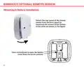
- Page 10: RS9055OUT optional remote sensor Mounting & battery installation Detach the rear panel of the remote sensor from the front panel by loosening the screws at the bottom of the cover. Use a screwdriver to open the battery cover from the arrow position.
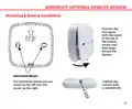
- Page 11: RS9055OUT optional remote sensor Mounting & battery installation Position the rear panel with the insert at the top of the remote sensor and then snap toward the bottom. For horizontal mount, put one screw on the left and one screw on the right. Tighten the screws with a screwdriver.
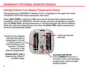
- Page 12: RS9055OUT optional remote sensor Getting to know your remote temperature sensor The temperature of RS9055OUT remote sensor is displayed in the upper left corner of RS9423T. When heat pump is selected to on, the RS9055OUT remote sensor induction temperature will determine the heating method. When the induction temperature is greater than the dual fuel setting temperature, it will automatically use electric heating. When the induction temperature is less than the dual fuel setting temperature, the fuel is automatically heated. Install two AA alkaline batteries into the battery compartment. Be sure to match positive ends of batteries with positive battery terminals in the battery compartment. SENSOR BATT LOW is displayed on RS9423T at low voltage. Press CONNECT button for 3 seconds to enter code learning configuration mode.
- Page 13: Caution: Electrical hazard. Disconnect power before installing this product. If you are replacing a thermostat, make note of the terminal connections on the thermostat that is being replaced. Loosen the terminal block screws. Insert wires then re-tighten the terminal block screws. Do not over-tighten terminal screws! Maximum torque is 6 in-lbs. Over-tightening terminal block screws can damage the terminal block. A damaged terminal block may prevent the thermostat from fitting on the faceplate and could cause system operation issues. Place nonflammable insulation into the wall opening to prevent drafts.
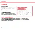
- Page 14: Wiring tips provide essential guidance for installation. The common wire is optional when the thermostat is powered by batteries. For heat pump systems without auxiliary or emergency heat, specific wiring instructions apply. A small piece of wire is needed to connect terminals E and W2 for emergency heat control. Use 18- to 22-gauge thermostat wire for wiring specifications. Shielded wire is not required for installation. The thermostat can be configured to operate a heat pump. Refer to the heat pump configuration section for detailed instructions.
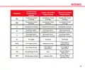
- Page 15: Wiring 2 Heat 2 Cool Conventional System 2 Heat 1 Cool Heat Pump System 3 Heat 2 Cool Heat Pump System Transformer Power (cooling) Transformer Power (heating) Reversing Valve/ Configurable Terminal Fan Relay First Stage of Heat & Cool
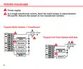
- Page 16: Wiring diagrams Power supply In a single-transformer system, leave the metal jumper in place between RH and RC. Remove the jumper in two-transformer systems. Typical 2H/2C system: 1 transformer Typical cool-only system with fan
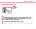
- Page 17: Wiring diagrams are provided for reference. A typical heat only system with a fan is illustrated. In heat pump systems without an emergency heat relay, a jumper can be used between E and W2. This setup allows the thermostat to function as a single stage control for emergency heat operation. Either O or B terminals can be used for the reversing valve. There is an option for a 24V AC common connection when the thermostat is powered by batteries.
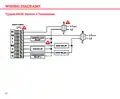
- Page 18: Wiring diagrams Typical 2H/2C system: 2 transformer
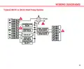
- Page 19: Wiring diagrams Typical 3H/2C or 2H/1C heat pump system
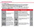
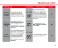
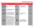
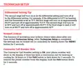
- Page 20: Technician setup involves pressing the MENU button and holding the TECHNICIAN SETUP button for 3 seconds to prevent accidental access by homeowners. Installer settings can be configured using the provided table, with keys to change settings and navigate steps. Press the DONE key only when exiting the Technician Setup options. To enter code learning configuration mode, press FAN and then the CONNECT button for 3 seconds. Successful code learning will display SUCCESS and stop the red light from flashing. The filter change reminder can be adjusted from OFF to 2000 hours in 50-hour increments. The OFF setting disables the filter change reminder feature. Room temperature calibration allows adjustment of the display to read up to 4° above or below the factory calibrated temperature. The thermostat can be set to read a specific temperature instead of the factory setting. These steps ensure proper configuration and functionality of the system.
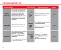
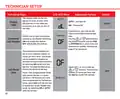
- Page 21: Technician setup involves several key steps. The LCD will display relevant information during the setup process. Adjustment options are available for various settings. The minimum compressor runtime can be adjusted from OFF to 3, 4, or 5 minutes. Selecting a minimum runtime helps protect the compressor from short cycling. The compressor short cycle delay setting prevents it from turning on for 5 minutes after being turned off. This delay setting can be disabled by selecting OFF. The cooling differential is factory preset at 0.5°. The cooling system activates when room temperature increases by the set differential. The cooling differential setting is adjustable from 0.2°F to 2°F.
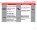
- Page 22: Technician setup involves several steps for proper configuration. The LCD will display relevant information during the setup process. The heating differential is factory preset at 0.4°, activating the heating system when the room temperature drops by this amount. If the heating system activates too frequently, consider increasing the temperature differential. The heating differential setting can be adjusted between 0.2°F and 2°F. The thermostat can be configured for conventional systems or heat pump systems. In heat pump mode, emergency heat is available. Different application configurations include HEAT OFF – COOL ON, HEAT OFF – COOL OFF, and HEAT OFF – COOL AUTO. Users can select the desired application using the appropriate buttons until it is displayed. The thermostat's functionality can be tailored to specific heating and cooling needs.
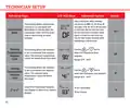
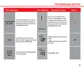
- Page 23: Technician setup Tech setup steps The thermostat can be configured to operate up to a 2H/2C conventional heat pump system. Use the key to first select stages of heat, press next - then select stages of cool. Stages of heat will use Y1 and Y2 as 1st and 2nd stage of heat. This feature is only shown if heat pump is on. When the heat pump is on and the remote sensor induction temperature is greater than the dual fuel setting. The dual fuel setting can be adjusted between 30°F to 70°F. Select the temperature point for automatic switching between oil and electricity. When the remote sensor induction temperature is less than the dual fuel setting temperature, oil will be utilized.
- Page 24: Technician setup Tech setup steps LCD will show Adjustment options The cooling fan delay setting can be set to OFF, 15, 30, 60, or 90 seconds. This setting delays the fan from coming on in cool mode and keeps it running after the compressor shuts off for a short time to save energy in some systems. This setting allows the installer to set a maximum heat setpoint value. The setpoint temperature cannot be raised above 90°F. This setting allows the installer to set a minimum cool setpoint value. The setpoint temperature cannot be below 41°F. Select F for Fahrenheit temperature display or select C for Celsius display.
- Page 25: Technician setup Tech setup steps LCD will show Adjustment options Select a 12 or 24 hour clock setting. Select GAS or ELECT depending on the type of furnace. This setting will start heating early to bring the temperature to its programmed setpoint by the beginning of the WAKE period. This thermostat can be configured to have 7 Day, 5+1+1 programmed or be non-programmable. If 7 Day is selected, all seven days will need to be programmed individually. Use the key to select 7d for 7 day, 5d for 5+1+1, or Od for non-programmable.
- Page 26: Technician setup involves several steps for configuration. The LCD will display various options during the setup process. Adjustment options include configuring the display light settings. The display light can be set to come on only when a key is pressed or to stay on continuously. You can input your contractor call number in the display. The fan can be configured to run a selected number of cycles per hour. This fan mode can be enabled or disabled during normal operation. The IAQ mode allows for programming the fan to operate 1-4 cycles per hour. Once programmed, the IAQ mode can be enabled with the fan key. Disabling the IAQ mode can be done by selecting ON or AUTO with the fan key.
- Page 27: Technician setup Tech setup steps LCD will show adjustment options Select 1, 5, 10, 15, 20, 30 or 45 minutes. When IAQ fan mode is enabled, the thermostat will ensure the fan runs at least the selected number of minutes for each IAQ mode cycle. This setting allows for the selection of the minimum number of minutes that the fan will run for each IAQ mode cycle. If ON is selected, the noise will sound. An audible noise will sound when any key is depressed unless this setting is in OFF mode. If OFF is selected, there will be no sound. This step resets all WiFi settings to factory default.
- Page 28: Technician setup allows for configuration of various settings. The second stage will turn on at 2x the differential setting and turn off at 1x the differential setting. For example, if the differential is 0.5°F for heating and the thermostat is set at 70°F, the first stage will turn on at approximately 69.5°F and turn off at approximately 70.5°F. The second stage will turn on at 69°F and turn off at approximately 69.5°F. If the third stage is used, it will turn on at 68.5°F and turn off at approximately 69°F. Keypad lockout can be activated after exiting Technician Setup. Settings can be locked out or unlocked by holding down the MENU button for 3 seconds. If the Contractor Call Number setting is ON, your phone number will show in the display during a continuous call for heating or cooling for 24 hours. To remove the phone number from the display, hold the FAN button down for 3 seconds.
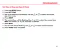
- Page 29: Set time of day and day of week. Press the MENU button. Press SET TIME. Day of the week will be flashing. Use the or to select the current day of the week. Press NEXT. The current hour will be flashing. Use the or to select the current hour. Press NEXT. Press DONE when completed.
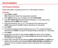
- Page 30: Set program schedule Follow these steps to customize your 5+1+1 or 7-day program schedule. Select heat or cool. Heat and cool need to be programmed separately. Press menu (if menu does not appear first, press run sched). Press set sched. Time will be flashing. Use to make your time selection for the wake time period. The setpoint temperature will be flashing. Use to make your setpoint selection for the wake time period. Repeat steps for the weekday leave, return, and sleep time periods. Repeat steps for Saturday and Sunday wake, leave, return, and sleep time periods for the 5+1+1 program schedule.
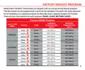
- Page 31: Factory default program Robertshaw RS9423T thermostats are shipped with an energy saving default program. The thermostat can be programmed to have all the weekdays the same, the same setpoints for all weekdays or a separate program for Saturday and a separate program for Sunday. There are four time periods for each program (Wake, Leave, Return, Sleep). Setpoint temperature (heat) and setpoint temperature (cool) are defined for each day of the week. Events are scheduled at specific times: 6 a.m., 8 a.m., 6 p.m., and 10 p.m. Temperature settings include 70°F (21°C) for heat and 75°F (24°C) for cool during wake times. Different temperature settings apply for leave, return, and sleep periods. The default program includes specific temperatures for weekdays, Saturday, and Sunday. The thermostat allows for customization of temperature settings based on user preferences.
- Page 32: Page 32

ENGO CONTROLS E10-B Wi-Fi Thermostat User Guide

heatit Z-TRM6 DC Z Wave Electronic Thermostat Instruction Manual

Fantini cosmi C820RQ Dual Power Room Thermostat Instruction Manual

homematic IP HmIP-BWTH-A Wall Thermostat Installation Guide

Danfoss UT 72-UT 73 Universal Thermostat Installation Guide

ENGO Controls EONE230W Internet Controlled Thermostat User Guide

SALUS Wired Thermostat Installation Guide

Danfoss DEVIreg 330 Electronic Thermostat Installation Guide

Honeywell RTHL3550 Non-programmable Thermostat Installation Guide

Honeywell Home DT4R 1 Channel Wireless Spare Room Thermostat Instruction Manual