Home > Homematic IP > homematic IP HmIP-BWTH-A Wall Thermostat Installation Guide

homematic IP HmIP-BWTH-A Wall Thermostat Installation Guide

Installations- und  
Bedienungsanleitung  
Installation instruction and  
operating manual  
Wandthermostat mit Schaltausgang – S. 2  
für Markenschalter, anthrazit  
Wall Thermostat with switching  
output – for brand switches,  
anthracite  
p. 47  
IP-BWTH-A  
GeneralDetails
Namehomematic IP HmIP-BWTH-A Wall Thermostat Installation Guide
MakeHomematic IP
LanguageEnglish
FiletypePDF (Download)
File size3.59 MB
Download PDF
1 Star2 Stars3 Stars4 Stars5 Stars (1 votes, average: 5.00 out of 5)
Loading...
homematic IP HmIP-eTRV-2 Radiator Thermostat Instruction Manual
homematic IP HmIP-WTH-B-2 Wall Thermostat Installation Guide
homematic IP TRV-E-A Monday Radiator Thermostat Instruction Manual
homematic IP HAP Radiator Thermostat Instruction Manual
homematic IP HmIP-eTRV-F Radiator Thermostat Instruction Manual
Homematic IP HmIP-WTH-B Wireless Wall Thermostat Instruction Manual
homematic IP HmIP-eTRV-E Series Radiator Thermostat Evo Installation Guide
Homematic IP BMOAONSUT Radiator Thermostat User Manual
homematic IP C-2 Radiator Thermostat Instruction Manual
homematic IP IP HmIP-eTRV-CL Radiator Thermostat Instruction Manual

homematic IP HmIP-BWTH-A Wall Thermostat Installation Guide
Get the free PDF manual for the homematic IP HmIP-BWTH-A Wall Thermostat Installation Guide and access setup steps, usage instructions, and troubleshooting tips. 👉 View online or download now to keep your thermostat running smoothly!
homematic IP HmIP-BWTH-A Wall Thermostat Installation Guide Overview

Summary of Contents

  • Page 1: Installation instruction and operating manual Wall thermostat with switching output – for brand switches, anthracite
  • Page 2: Lieferumfang Homematic IP Wandthermostat mit Schaltausgang – für Markenschalter, anthrazit Wechselrahmen Spannungsversorgungseinheit Schrauben 3,2 x 15 mm Schrauben 3,2 x 25 mm Bedienungsanleitung Dokumentation © 2023 eQ-3 AG, Deutschland Alle Rechte vorbehalten. Ohne schriftliche Zustimmung des Herausgebers darf diese Anleitung auch nicht auszugsweise in irgendeiner Form reproduziert werden. Änderungen im Sinne des technischen Fortschritts können ohne Vorankündigung vorgenommen werden.
  • Page 3: Page 3
  • Page 4: Page 4
  • Page 5: Page 5
  • Page 6: Inhaltsverzeichnis Hinweise zur Anleitung Gefahrenhinweise Funktion und Geräteübersicht Allgemeine Systeminformationen Inbetriebnahme Installationshinweise Verhalten nach Einschalten der Netzspannung Anlernen Betriebsmodi und Konfiguration Automatikbetrieb
  • Page 7: Konfiguration des Fußbodenheizungsaktors Bedienung Fehlerbehebung Befehl nicht bestätigt Duty Cycle Fehlercodes und Blinkfolgen Wiederherstellung der Werkseinstellungen Wartung und Reinigung Allgemeine Hinweise zum Funkbetrieb Technische Daten
  • Page 8: Hinweise zur Anleitung Lesen Sie diese Anleitung sorgfältig, bevor Sie Ihre Homematic IP Geräte in Betrieb nehmen. Bewahren Sie die Anleitung zum späteren Nachschlagen auf. Wenn Sie das Gerät anderen Personen zur Nutzung überlassen, übergeben Sie auch diese Anleitung. Benutzte Symbole: Achtung! Hier wird auf eine Gefahr hingewiesen. Hinweis. Dieser Abschnitt enthält zusätzliche wichtige Informationen! Gefahrenhinweise Öffnen Sie das Gerät nicht. Es enthält keine durch den Anwender zu wartenden Teile. Im Fehlerfall lassen Sie das Gerät von einer Fachkraft prüfen. Aus Sicherheits- und Zulassungsgründen (CE) ist das eigenmächtige Umbauen und/oder Verändern des Gerätes nicht gestattet.
  • Page 9: Gefahrenhinweise Betreiben Sie das Gerät nur in trockener sowie staubfreier Umgebung. Das Gerät ist kein Spielzeug. Erlauben Sie Kindern nicht damit zu spielen. Lassen Sie das Verpackungsmaterial nicht achtlos liegen. Bei Sach- oder Personenschäden, die durch unsachgemäße Handhabung verursacht werden, übernehmen wir keine Haftung. Das Gerät darf nur für ortsfeste Installationen verwendet werden. Das Gerät ist sicher innerhalb einer festen Installation zu fixieren. Der Aktor ist Teil der Gebäudeinstallation. Bei der Planung und Errichtung sind die einschlägigen Normen und Richtlinien des Landes zu beachten. Der Betrieb des Gerätes ist ausschließlich am 230 V/50 Hz-Wechselspannungsnetz zulässig.
  • Page 10: Gefahrenhinweise Arbeiten am 230 V-Netz dürfen nur von einer Elektrofachkraft erfolgen. Es sind die geltenden Unfallverhütungsvorschriften zu beachten. Zur Vermeidung eines elektrischen Schlages am Gerät, schalten Sie bitte die Netzspannung frei. Bei Nichtbeachtung der Installationshinweise können Brand oder andere Gefahren entstehen. Beachten Sie beim Anschluss an die Geräteklemmen die hierfür zulässigen Leitungen und Querschnitte. Beachten Sie vor Anschluss eines Verbrauchers die technischen Daten, insbesondere die maximal zulässige Anschlussleistung. Alle Lastangaben beziehen sich auf ohmsche Lasten. Belasten Sie den Aktor nur bis zur angegebenen Leistungsgrenze. Eine Überlastung kann zur Zerstörung des Gerätes, zu einem Brand oder zu einem elektrischen Schlag führen. Vor dem Anschließen des Aktors muss die Sicherung im Sicherungskasten herausgenommen werden.
  • Page 11: Funktion und Geräteübersicht Das Gerät ist nicht zum Freischalten geeignet. Das Gerät ist nur für den Einsatz in wohnungsähnlichen Umgebungen geeignet. Jeder andere Einsatz, als der in dieser Bedienungsanleitung beschriebene, ist nicht bestimmungsgemäß und führt zu Gewährleistungs- und Haftungsausschluss. Der Homematic IP Wandthermostat mit Schaltausgang für Markenschalter verfügt über einen Relais-Ausgang zur Steuerung von 230 V-Fußbodenheizungsstellantrieben. Über die Steuerung des Relais-Ausgangs wird die Raumtemperatur entsprechend Ihrer individuell festgelegten Heizprofile reguliert. Zusätzlich kann der Homematic IP Wandthermostat in Verbindung mit Homematic IP Fußbodenheizungsaktoren oder Homematic IP Heizkörperthermostaten für Ihre konventionellen Heizkörper eingesetzt werden. Er sorgt so für eine bedarfsgerechte Regulierung der Temperatur auf Raumebene.
  • Page 12: Der Wandthermostat misst die Temperatur und Luftfeuchtigkeit im Raum und steuert auf Basis der aktuellen Werte den Relais-Ausgang. Die Steuerung und Konfiguration kann direkt am Homematic IP Wandthermostaten oder alternativ über die kostenlose Homematic IP App erfolgen. Sie können den bereits vorhandenen Wandthermostaten Ihrer bestehenden Installation einfach gegen den Homematic IP Wandthermostaten austauschen. Das Gerät kann in der Unterputzdose installiert werden. Durch die Nutzung von Bauteilen der bereits vorhandenen Schalterserien wird der Installationsaufwand auf ein Minimum reduziert. Das Design von bereits installierten Schalterserien bleibt unverändert, da vorhandene Rahmen weiter genutzt werden können. Geräteübersicht: Wechselrahmen, Elektronikeinheit (Thermostat), Display, Systemtaste (Anlerntaste und LED), Stellrad, Spannungsversorgungseinheit.
  • Page 13: Funktion und Geräteübersicht Displayübersicht Soll-/Ist-Temperatur Luftfeuchtigkeit Warnung für Betauung Fenster-auf-Symbol Spannungsversorgung Funkübertragung Boost-Funktion Manueller Betrieb
  • Page 14: Allgemeine Systeminformationen Dieses Gerät ist Teil des Homematic IP Smart-Home-Systems und kommuniziert über das Homematic IP Funkprotokoll. Alle Geräte des Systems können komfortabel und individuell per Smartphone über die Homematic IP App konfiguriert werden. Alternativ haben Sie die Möglichkeit, Homematic IP Geräte über die Zentrale CCU3 oder in Verbindung mit vielen Partnerlösungen zu betreiben. Welcher Funktionsumfang sich innerhalb des Systems im Zusammenspiel mit weiteren Komponenten ergibt, entnehmen Sie bitte dem Homematic IP Anwenderhandbuch. Alle technischen Dokumente und Updates finden Sie stets aktuell unter www.homematic-ip.com. Inbetriebnahme Bitte lesen Sie diesen Abschnitt erst vollständig, bevor Sie mit der Installation beginnen. Bitte notieren Sie sich vor der Installation die auf dem Gerät angebrachte Gerätenummer (SGTIN) und den Installationsort.
  • Page 15: Inbetriebnahme Installation nur durch Personen mit einschlägigen elektrotechnischen Kenntnissen und Erfahrungen. Durch eine unsachgemäße Installation gefährden Sie Ihr eigenes Leben und das Leben der Nutzer der elektrischen Anlage. Mit einer unsachgemäßen Installation riskieren Sie schwere Sachschäden, z. B. durch Brand. Es droht für Sie die persönliche Haftung bei Personen- und Sachschäden. Wenden Sie sich an einen Elektroinstallateur. Erforderliche Fachkenntnisse für die Installation: Die anzuwendenden „5 Sicherheitsregeln“: Freischalten; gegen Wiedereinschalten sichern; Spannungsfreiheit feststellen; Erden und Kurzschließen; benachbarte, unter Spannung stehende Teile abdecken oder abschranken. Auswahl des geeigneten Werkzeuges, der Messgeräte und ggf. der persönlichen Schutzausrüstung. Auswertung der Messergebnisse. Auswahl des Elektro-Installationsmaterials zur Sicherstellung der Abschaltbedingungen.
  • Page 16: Inbetriebnahme IP-Schutzarten Einbau des Elektroinstallationsmaterials Art des Versorgungsnetzes (TN-System, IT-System, TT-System) und die daraus folgenden Anschlussbedingungen Die Installation darf nur in handelsüblichen Schalterdosen gemäß DIN 49073-1 erfolgen. Beachten Sie bei der Installation die Gefahrenhinweise gemäß „2 Gefahrenhinweise“ auf Seite 9. Zugelassene Leitungsquerschnitte zum Anschluss an den Wandthermostaten sind: Starre Leitung [mm²] 0,75 – 1,50, Flexible Leitung mit und ohne Aderendhülse [mm²] 0,75 – 1,50. Für die Installation des Wandthermostats gehen Sie wie folgt vor: Schalten Sie die Haussicherung des Stromkreises ab. Entfernen Sie die Abdeckung Ihres bestehenden Wandthermostaten.
  • Page 17: Inbetriebnahme Um die Demontage zu erleichtern, kann ein flacher spitzer Gegenstand, z. B. ein Schlitzschraubendreher, zur Hilfe genommen werden. Lösen Sie die Verdrahtung und entfernen Sie den vorhandenen Wandthermostaten. Schließen Sie den Außenleiter an die Anschlussklemme L (G) der Spannungsversorgungseinheit an. Schließen Sie den Neutralleiter an die Anschlussklemme N (H) der Spannungsversorgungseinheit an. Schließen Sie die Leitung des Ventilantriebs an die Anschlussklemme 1 (I) der Spannungsversorgungseinheit an. Setzen Sie die Spannungsversorgungseinheit in die Unterputzdose ein und befestigen Sie ihn mittels der mitgelieferten Schrauben an der Unterputzdose. Setzen Sie den Rahmen Ihrer Installation oder den mitgelieferten Wechselrahmen (A) auf die Spannungsversorgungseinheit auf. Setzen Sie die Elektronikeinheit (B) des Wandthermostats in den Rahmen ein. Schalten Sie die Haussicherung des Stromkreises wieder ein, um den Anlernmodus des Gerätes zu aktivieren.
  • Page 18: Inbetriebnahme Verhalten nach Einschalten der Netzspannung In den ersten 3 Minuten nach dem Einschalten der Netzspannung befindet sich der Wandthermostat im Anlernmodus. In den ersten 10 Minuten nach dem Einschalten der Netzspannung befindet sich der Wandthermostat im Startmodus. In dieser Zeit wird das Relais angesteuert. In den folgenden 20 Minuten wird das Relais über eine 2-Punkt-Regelung betrieben. Nach Ablauf der 20 Minuten wird das Relais über eine PI-Regelung mit PWM-Ausgang betrieben. Wollen Sie den Wandthermostaten im Stand-Alone-Betrieb betreiben, können Sie bei Kapitel 6 fortfahren. Anlernen Bitte lesen Sie diesen Abschnitt erst vollständig, bevor Sie mit dem Anlernen beginnen. Damit der Wandthermostat in Ihr System integriert werden kann, muss er zunächst angelernt werden.
  • Page 19: Inbetriebnahme Sie können den Wandthermostaten zur Steuerung Ihrer Fußbodenheizung entweder direkt an den Homematic IP Fußbodenheizungsaktor oder zur Steuerung des gesamten Raumklimas an den Homematic IP Access Point anlernen. Beim direkten Anlernen erfolgt die Konfiguration am Gerät und beim Anlernen an den Access Point über die Homematic IP App. Halten Sie beim Anlernen einen Mindestabstand von 50 cm zwischen den Geräten ein. Sie können den Anlernvorgang durch erneute kurze Betätigung der Systemtaste abbrechen. Wenn kein Anlernen erfolgt, wird der Anlernmodus automatisch nach 30 Sekunden beendet. Wenn Sie den Wandthermostaten an einen Homematic IP Fußbodenheizungsaktor anlernen möchten, müssen die beiden zu verknüpfenden Geräte in den Anlernmodus gebracht werden.
  • Page 20: Inbetriebnahme Die Geräte-LED beginnt orange zu blinken. Weitere Informationen dazu entnehmen Sie bitte der Bedienungsanleitung des Fußbodenheizungsaktors. Drücken Sie die Systemtaste des Wandthermostats für mindestens 4 Sekunden, um den Anlernmodus zu aktivieren. Die Geräte-LED blinkt orange. Erfolgreiches Anlernen wird durch grünes Blinken der Geräte-LED signalisiert. War der Anlernvorgang nicht erfolgreich, leuchtet die Geräte-LED rot auf. Richten Sie zunächst Ihren Homematic IP Access Point über die Homematic IP App ein, um weitere Homematic IP Geräte im System nutzen zu können. Ausführliche Informationen dazu finden Sie in der Bedienungsanleitung des Access Points. Öffnen Sie die Homematic IP App auf Ihrem Smartphone. Wählen Sie den Menüpunkt „Gerät anlernen“ aus. Nach der Installation ist der Anlernmodus für 3 Minuten aktiv.
  • Page 21: Betriebsmodi und Konfiguration Der Anlernmodus kann manuell für weitere 3 Minuten gestartet werden. Das Gerät erscheint automatisch in der Homematic IP App. Zur Bestätigung geben Sie die letzten vier Ziffern der Gerätenummer ein oder scannen Sie den QR-Code. Die Gerätenummer finden Sie auf dem Aufkleber im Lieferumfang oder direkt am Gerät. Warten Sie, bis der Anlernvorgang abgeschlossen ist. Zur Bestätigung eines erfolgreichen Anlernvorgangs leuchtet die LED grün. Das Gerät ist nun einsatzbereit. Leuchtet die LED rot, versuchen Sie es erneut. Wählen Sie in der App aus, in welchen Lösungen Ihr Gerät eingesetzt werden soll. Durch das Anlernen des Wandthermostats am Homematic IP Access Point wird das Menü des Wandthermostats ausgeblendet.
  • Page 22: Betriebsmodi und Konfiguration Nach der Installation können Sie über das Konfigurationsmenü Einstellungen vornehmen, um das Gerät an Ihre persönlichen Bedürfnisse anzupassen. Drücken Sie lange auf das Stellrad, um das Konfigurationsmenü zu öffnen. Wählen Sie das gewünschte Symbol durch Drehen und kurzes Drücken des Stellrads aus. Durch langes Drücken des Stellrads gelangen Sie zur vorherigen Ebene zurück. Wenn für mehr als 1 Minute keine Betätigung am Gerät erfolgt, schließt sich das Menü automatisch. Automatikbetrieb Manueller Betrieb Urlaubsmodus Bediensperre Antriebstyp und häusliche Gegebenheiten
  • Page 23: Betriebsmodi und Konfiguration Programmierung der Heizprofile Datum und Uhrzeit Offset-Temperatur Auswahl der gewünschten Temperaturanzeige Konfiguration des Fußbodenheizungsaktors Verbindungstest Automatikbetrieb Im Automatikbetrieb erfolgt die Temperaturregelung gemäß dem eingestellten Wochenprofil. Manuelle Änderungen über das Stellrad bleiben bis zum nächsten Schaltzeitpunkt aktiv. Um den Automatikbetrieb zu aktivieren, drücken Sie lange auf das Stellrad, um das Konfigurationsmenü zu öffnen.
  • Page 24: Betriebsmodi und Konfiguration Manueller Betrieb Im manuellen Betrieb erfolgt die Temperaturregelung gemäß der am Stellrad eingestellten Temperatur. Die Temperatur bleibt bis zur nächsten manuellen Änderung erhalten. Um den manuellen Betrieb zu aktivieren, drücken Sie lange auf das Stellrad, um das Konfigurationsmenü zu öffnen. Wählen Sie durch Drehen des Stellrads das Symbol aus und bestätigen Sie die Auswahl durch kurzes Drücken des Stellrads. Drehen Sie das Stellrad, um die gewünschte Temperatur einzustellen. Sie können das Ventil/Relais schließen/ausschalten bzw. öffnen/anschalten, indem Sie das Stellrad bis zum Anschlag drehen. Urlaubsmodus Der Urlaubsmodus kann genutzt werden, wenn für einen bestimmten Zeitraum eine feste Temperatur gehalten werden soll. Um den Urlaubsmodus einzustellen, drücken Sie lange auf das Stellrad, um das Konfigurationsmenü zu öffnen. Wählen Sie durch Drehen des Stellrads das Symbol aus und bestätigen Sie die Auswahl.
  • Page 25: Betriebsmodi und Konfiguration Stellen Sie durch Drehen des Stellrads Start-Uhrzeit und -Datum ein und bestätigen Sie die Auswahl durch kurzes Drücken des Stellrads. Das „S“ zeigt an, dass es sich um die Startzeit handelt. Stellen Sie durch Drehen des Stellrads End-Uhrzeit und -Datum ein und bestätigen Sie die Auswahl durch kurzes Drücken des Stellrads. Das „E“ zeigt an, dass es sich um die Endzeit handelt. Stellen Sie durch Drehen des Stellrads die Temperatur ein, die während der definierten Zeit gehalten werden soll und bestätigen Sie die Auswahl durch kurzes Drücken des Stellrads. Wählen Sie durch Drehen des Stellrads aus, für welche Räume der Urlaubsmodus aktiviert werden soll. Auswahl „OnE“: Der Urlaubsmodus wird für den aktuellen Wandthermostaten aktiviert. Auswahl „ALL“: Der Urlaubsmodus wird für alle Wandthermostate, die an den Fußbodenheizungsaktor angelernt sind, aktiviert.
  • Page 26: Betriebsmodi und Konfiguration Die Bedienung am Gerät kann gesperrt werden, um das ungewollte Verändern von Einstellungen zu verhindern. Um die Bediensperre zu aktivieren bzw. deaktivieren, drücken Sie lange auf das Stellrad, um das Konfigurationsmenü zu öffnen. Wählen Sie durch Drehen des Stellrads das Symbol aus und bestätigen Sie die Auswahl durch kurzes Drücken des Stellrads. Wählen Sie „On“, um die Bediensperre zu aktivieren oder „OFF“, um die Bediensperre zu deaktivieren. Ist die Bediensperre aktiviert, können Sie über das Konfigurationsmenü nur den Menüpunkt für die Bediensperre aufrufen. Unter diesem Menüpunkt können Sie den Antriebstyp auswählen. Drücken Sie lange auf das Stellrad, um das Konfigurationsmenü zu öffnen. Wählen Sie durch Drehen des Stellrads den gewünschten Antriebstyp aus.
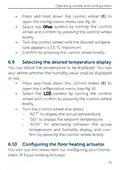
  • Page 27: Betriebsmodi und Konfiguration Wählen Sie durch Drehen des Stellrads „Unit“ und „nc“ oder „no“ für normally closed oder normally open aus. Wählen Sie „ArEA“ und eine Nummer von 0 bis 4 mit folgender Bedeutung für Ihre häuslichen Gegebenheiten aus. Nummer 0: FBH Standard Nummer 1: FBH Niedrigenergie Nummer 2: Radiator Nummer 3: Konvektor passiv Nummer 4: Konvektor aktiv Programmierung der Wochenprofile Unter diesem Menüpunkt können Sie Einstellungen für Ihre Heiz- bzw. Kühlprofile vornehmen und Wochenprofile nach Ihren eigenen Bedürfnissen erstellen. Drücken Sie lange auf das Stellrad, um das Konfigurationsmenü zu öffnen.
  • Page 28: Betriebsmodi und Konfiguration Wählen Sie durch Drehen des Stellrads „type“ für das Auswählen zwischen Heizen („HEAT“) oder Kühlen („COOL“). „Pr.nr“ für das Auswählen der Wochenprofilnummer („nr. 1, nr. 2 ... nr. 6“). „Pr.Ad“ für das individuelle Einstellen des Wochenprofils. „OSSF“ zum Aktivieren („On“) bzw. Deaktivieren („OFF“) der Optimum-Start-/Stop-Funktion. Sie können Ihre Fußbodenheizung im Winter zum Heizen und im Sommer zum Kühlen verwenden. Wählen Sie im Menüpunkt „type“ durch Drehen des Stellrads „HEAT“ für Heizen oder „COOL“ für Kühlen aus. Sie können zwischen den 6 folgenden, bereits vorkonfigurierten Profilen wählen. Wählen Sie im Menüpunkt „Pr.nr.“ durch Drehen des Stellrads die Nummer des gewünschten Profils aus.
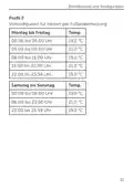
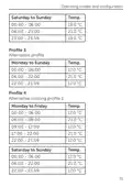
  • Page 29: Betriebsmodi und Konfiguration Ist das gewählte Profil ein Heizprofil, wird geheizt, sobald die Raumtemperatur unter den festgelegten Wert fällt. Ist das gewählte Profil ein Kühlprofil, wird gekühlt, sobald die Raumtemperatur über den festgelegten Wert steigt. Wird im Menü von „Heizen“ auf „Kühlen“ gewechselt, wird automatisch von Profil 1 auf 4, von Profil 2 auf 5 und von Profil 3 auf 6 gewechselt. Profil 1 Vorkonfiguriert für Heizen per Heizkörperthermostat. Montag bis Freitag: 00:00 bis 06:00 Uhr, 06:00 bis 09:00 Uhr, 09:00 bis 17:00 Uhr, 17:00 bis 22:00 Uhr, 22:00 bis 23:59 Uhr. Temperaturen: 17,0 °C, 21,0 °C, 17,0 °C, 21,0 °C, 17,0 °C. Samstag bis Sonntag: 00:00 bis 06:00 Uhr, 06:00 bis 22:00 Uhr, 22:00 bis 23:59 Uhr. Temperaturen: 17,0 °C, 21,0 °C, 17,0 °C.
  • Page 30: Betriebsmodi und Konfiguration Profil 2 Vorkonfiguriert für Heizen per Fußbodenheizung Montag bis Freitag Temperaturen für verschiedene Zeiträume: Samstag bis Sonntag Temperaturen für verschiedene Zeiträume:
  • Page 31: Betriebsmodi und Konfiguration Profil 3 Alternatives Heizprofil Montag bis Sonntag Temperaturen: 17,0 °C, 21,0 °C Profil 4 Alternatives Kühlprofil 1 Montag bis Freitag Temperaturen: 17,0 °C, 21,0 °C Samstag bis Sonntag Temperaturen: 17,0 °C, 21,0 °C
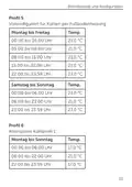
  • Page 32: Betriebsmodi und Konfiguration Profil 5 Vorkonfiguriert für Kühlen per Fußbodenheizung Montag bis Freitag Temperaturen für verschiedene Zeiträume: - 00:00 bis 05:00 Uhr: 23,0 °C - 05:00 bis 08:00 Uhr: 21,0 °C - 08:00 bis 15:00 Uhr: 23,0 °C - 15:00 bis 22:00 Uhr: 21,0 °C - 22:00 bis 23:59 Uhr: 23,0 °C Samstag bis Sonntag Temperaturen für verschiedene Zeiträume: - 00:00 bis 06:00 Uhr: 23,0 °C - 06:00 bis 23:00 Uhr: 21,0 °C - 23:00 bis 23:59 Uhr: 23,0 °C Profil 6 Alternatives Kühlprofil 1 Montag bis Sonntag Temperaturen für verschiedene Zeiträume: - 00:00 bis 06:00 Uhr: 17,0 °C - 06:00 bis 22:00 Uhr: 21,0 °C - 22:00 bis 23:59 Uhr: 17,0 °C
  • Page 33: Betriebsmodi und Konfiguration Im Wochenprofil lassen sich für jeden Wochentag des gewählten Heiz- bzw. Kühlprofils separat bis zu 6 Heizphasen individuell einstellen. Die Programmierung erfolgt für die ausgewählten Tage, wobei für einen Zeitraum von 00:00 bis 23:59 Uhr Temperaturen hinterlegt werden können. Wählen Sie im Menüpunkt „Pr.Ad“ durch Drehen des Stellrads die Nummer des gewünschten Profils aus und bestätigen Sie die Auswahl. Wählen Sie unter „dAY“ durch Drehen des Stellrads bestimmte Wochentage, alle Werktage, das Wochenende oder die gesamte Woche für Ihr Heizprofil aus. Bestätigen Sie die Startzeit 00:00 Uhr durch kurzes Drücken des Stellrads. Wählen Sie durch Drehen des Stellrads die gewünschte Temperatur für die Startzeit aus und bestätigen Sie die Auswahl. Im Display wird die nächste Uhrzeit angezeigt. Sie können diese Zeit mit dem Stellrad verändern. Wählen Sie durch Drehen des Stellrads die gewünschte Temperatur für den nächsten Zeitraum aus und bestätigen Sie die Auswahl.
  • Page 34: Betriebsmodi und Konfiguration Wiederholen Sie diesen Vorgang, bis für den gesamten Zeitraum von 0:00 bis 23:59 Uhr Temperaturen hinterlegt sind. Optimum-Start-/Stop-Funktion Damit zur festgelegten Zeit die gewünschte Temperatur im Raum bereits erreicht wurde, können Sie die Optimum-Start-/Stop-Funktion aktivieren. Wählen Sie im Menüpunkt „OSSF“ durch Drehen des Stellrads „On“ für das Aktivieren oder „OFF“ für das Deaktivieren der Funktion aus und bestätigen Sie die Auswahl durch kurzes Drücken des Stellrads. Datum und Uhrzeit Um Datum und Uhrzeit einzustellen, gehen Sie wie folgt vor: Drücken Sie lange auf das Stellrad, um das Konfigurationsmenü zu öffnen. Wählen Sie durch Drehen des Stellrads das Symbol aus und bestätigen Sie die Auswahl durch kurzes Drücken des Stellrads. Stellen Sie durch Drehen des Stellrads Jahr, Monat, Tag und Uhrzeit ein und bestätigen Sie durch kurzes Drücken des Stellrads.
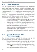
  • Page 35: Betriebsmodi und Konfiguration Offset-Temperatur Die Temperatur am Wandthermostaten wird gemessen, was zu Abweichungen im Raum führen kann. Eine Offset-Temperatur von bis zu 3.5 °C kann eingestellt werden, um dies auszugleichen. Werksseitig ist eine Offset-Temperatur von 0.0 °C eingestellt. Um die Offset-Temperatur individuell anzupassen, drücken Sie lange auf das Stellrad, um das Konfigurationsmenü zu öffnen. Wählen Sie das entsprechende Symbol aus und bestätigen Sie die Auswahl. Drehen Sie das Stellrad, bis die gewünschte Temperatur erscheint, und bestätigen Sie dies. Auswahl der gewünschten Temperaturanzeige Sie können festlegen, welche Temperatur und ob die Luftfeuchtigkeit im Display angezeigt werden soll. Drücken Sie lange auf das Stellrad, um das Konfigurationsmenü zu öffnen. Wählen Sie das entsprechende Symbol aus und bestätigen Sie die Auswahl.
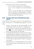
  • Page 36: Betriebsmodi und Konfiguration Wählen Sie durch Drehen des Stellrads „ACT“ für das Anzeigen der Ist-Temperatur, „SEt“ für das Anzeigen der Soll-Temperatur oder „ACtH“ für das Anzeigen der Ist-Temperatur und der aktuellen Luftfeuchtigkeit im Wechsel aus und bestätigen Sie Ihre Auswahl durch kurzes Drücken des Stellrads. Konfiguration des Fußbodenheizungsaktors Unter diesem Menüpunkt können Sie Einstellungen für Ihren Homematic IP Fußbodenheizungsaktor vornehmen. Drücken Sie lange auf das Stellrad, um das Konfigurationsmenü zu öffnen. Wählen Sie durch Drehen des Stellrads das Symbol aus und bestätigen Sie die Auswahl durch kurzes Drücken des Stellrads. Ist der Wandthermostat an mehr als einen Fußbodenheizungsaktor angelernt, wählen Sie mit dem Stellrad die gewünschte Fußbodenheizung aus. Wählen Sie aus, ob Sie Geräteparameter oder Kanalparameter konfigurieren wollen. Stellen Sie Vor- sowie Nachlaufzeiten der Pumpe, Eco-Temperaturen, Zeitintervalle etc. ganz individuell ein.
  • Page 37: Bedienung Weitere Informationen zu den Konfigurationsmöglichkeiten entnehmen Sie bitte der Bedienungsanleitung des Homematic IP Fußbodenheizungsaktors. Verbindungstest Sie können die Verbindung zwischen Ihrem Homematic IP Wandthermostaten und dem Homematic IP Fußbodenheizungsaktor überprüfen. Drücken Sie lange auf das Stellrad, um das Konfigurationsmenü zu öffnen. Wählen Sie durch Drehen des Stellrads das Symbol aus und bestätigen Sie die Auswahl durch kurzes Drücken des Stellrads. Nach der Konfiguration stehen Ihnen einfache Bedienfunktionen direkt am Gerät zur Verfügung. Befindet sich der Wandthermostat im Stand-by-Modus, müssen Sie vor der Bedienung einmal das Stellrad drücken, um ihn zu aktivieren.
  • Page 38: Fehlerbehebung Temperatur: Drehen Sie das Stellrad des Wandthermostats nach rechts oder links, um die Temperatur manuell zu verändern. Im Automatikbetrieb bleibt die manuell eingestellte Temperatur bis zum nächsten Schaltzeitpunkt bestehen. Boost-Funktion für Homematic IP Heizkörperthermostate: Drücken Sie das Stellrad des Wandthermostats kurz, um die Boost-Funktion für schnelles, kurzzeitiges Aufheizen des Heizkörpers zu aktivieren. Befehl nicht bestätigt: Bestätigt mindestens ein Empfänger einen Befehl nicht, leuchtet zum Abschluss der fehlerhaften Übertragung die LED rot auf. Grund für die fehlerhafte Übertragung kann eine Funkstörung sein.
  • Page 39: Fehlerbehebung kann folgende Ursachen haben: Empfänger nicht erreichbar, Empfänger kann Befehl nicht ausführen oder Empfänger defekt. Der Duty Cycle beschreibt eine gesetzlich geregelte Begrenzung der Sendezeit von Geräten im 868 MHz-Bereich. Das Ziel dieser Regelung ist es, die Funktion aller im 868 MHz-Bereich arbeitenden Geräte zu gewährleisten. Die maximale Sendezeit eines jeden Gerätes beträgt 1 % einer Stunde (also 36 Sekunden in einer Stunde). Die Geräte dürfen bei Erreichen des 1 %-Limits nicht mehr senden, bis diese zeitliche Begrenzung vorüber ist. Homematic IP Geräte werden zu 100 % normenkonform entwickelt und produziert. Im normalen Betrieb wird der Duty Cycle in der Regel nicht erreicht. Eine Überschreitung des Duty Cycle-Limits wird durch ein langes rotes Blinken der LED angezeigt. Die temporär fehlende Funktion des Gerätes äußert sich durch das Blinken der LED. Nach kurzer Zeit (max. 1 Stunde) ist die Funktion des Gerätes wiederhergestellt.
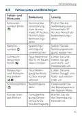
  • Page 40: Fehlercodes und Blinkfolgen Antennensymbol blinkt: Kommunikationsstörung zum Homematic IP Access Point/Fußbodenheizungsaktor. Prüfen Sie die Verbindung zum Homematic IP. Batteriesymbol: Spannungsversorgung unterbrochen. Stellen Sie die Spannungsversorgung wieder her. Luftfeuchtesymbol blinkt: Feuchtegrenze (60 %) im Raum überschritten. Lüften Sie und stellen Sie ggf. von Kühl- auf Heizbetrieb um. Betauungs- und Kühlsymbol blinken: Feuchteeingang bei Multi IO Box wurde aktiviert. Lüften Sie und stellen Sie ggf. von Kühl- auf Heizbetrieb um. Schlosssymbol: Bediensperre aktiv. Deaktivieren Sie die Bediensperre in der App/im Menü. Kurzes oranges Blinken: Funkübertragung/Sendeversuch/Datenübertragung. Warten Sie, bis die Übertragung beendet ist.
  • Page 41: Fehlerbehebung 1x langes grünes Leuchten bestätigt den Vorgang, und Sie können mit der Bedienung fortfahren. 1x langes rotes Leuchten bedeutet, dass der Vorgang fehlgeschlagen ist. Versuchen Sie es erneut. Kurzes oranges Blinken (alle 10 s) zeigt an, dass der Anlernmodus aktiv ist. Geben Sie die letzten vier Ziffern der Gerätenummer zur Bestätigung ein. 1x langes rotes Leuchten kann auf einen nicht bestätigten Befehl hinweisen oder das Duty Cycle-Limit erreicht sein. 6x langes rotes Blinken deutet darauf hin, dass das Gerät defekt ist. Achten Sie auf die Anzeige in Ihrer App oder wenden Sie sich an Ihren Fachhändler. 1x oranges Leuchten zeigt an, dass die Testanzeige erloschen ist, und Sie können fortfahren. 1x grünes Leuchten nach dem Einlegen der Batterien.
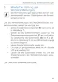
  • Page 42: Wiederherstellung der Werkseinstellungen Die Werkseinstellungen des Gerätes können wiederhergestellt werden. Dabei gehen alle Einstellungen verloren. Um die Werkseinstellungen des Wandthermostats wiederherzustellen, gehen Sie wie folgt vor: Ziehen Sie die Elektronikeinheit nach vorne ab. Setzen Sie die Elektronikeinheit wieder auf die Spannungsversorgungseinheit auf und halten Sie gleichzeitig die Systemtaste für 4 s gedrückt, bis die LED schnell orange zu blinken beginnt. Lassen Sie die Systemtaste wieder los. Drücken Sie die Systemtaste erneut für 4 s, bis die LED grün aufleuchtet. Lassen Sie die Systemtaste wieder los, um das Wiederherstellen der Werkseinstellungen abzuschließen. Das Gerät führt einen Neustart durch.
  • Page 43: Wartung und Reinigung Das Gerät ist wartungsfrei bis auf einen eventuell erforderlichen Batteriewechsel. Überlassen Sie eine Wartung oder Reparatur einer Fachkraft. Reinigen Sie das Gerät mit einem weichen, sauberen, trockenen und fusselfreien Tuch. Für die Entfernung von stärkeren Verschmutzungen kann das Tuch leicht mit lauwarmem Wasser angefeuchtet werden. Verwenden Sie keine lösemittelhaltigen Reinigungsmittel, da das Kunststoffgehäuse und die Beschriftung angegriffen werden können. Allgemeine Hinweise zum Funkbetrieb Die Funk-Übertragung wird auf einem nicht exklusiven Übertragungsweg realisiert, weshalb Störungen nicht ausgeschlossen werden können. Weitere Störeinflüsse können durch Schaltvorgänge, Elektromotoren oder defekte Elektrogeräte hervorgerufen werden. Die Reichweite in Gebäuden kann stark von der im Freifeld abweichen. Umwelteinflüsse wie Luftfeuchtigkeit und bauliche Gegebenheiten spielen eine wichtige Rolle.
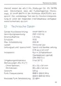
  • Page 44: Technische Daten Hiermit erklärt die eQ-3 AG, dass der Funkanlagentyp Homematic IP HmIP-BWTH-A der Richtlinie 2014/53/EU entspricht. Geräte-Kurzbezeichnung: HmIP-BWTH-A Versorgungsspannung: 230 V/50 Hz Stromaufnahme: 1 A max. Schutzart: IP20 Max. Schaltleistung: 230 W Lastart: ohmsche Last Installation: Nur in Schalterdosen (Gerätedosen) gemäß DIN 49073-1 Umgebungstemperatur: 0 bis 50 °C Abmessungen (B x H x T): 55 x 55 x 54 mm ohne Rahmen, 86 x 86 x 54 mm mit Rahmen Gewicht: 136 g Funk-Frequenzband: 868.0-868.6 MHz, 869.4-869.65 MHz Maximale Funk-Sendeleistung: 10 dBm
  • Page 45: Technische Daten Empfängerkategorie: SRD category 2 Typ. Funk-Freifeldreichweite: 130 m Duty Cycle: < 1 % pro h/< 10 % pro h Wirkungsweise: Verschmutzungsgrad: Typ 1.B Kugeldruckprüfung: 125 °C Stehstoßspannung: 4000 V Unabhängig montiertes elektronisches RS Technische Änderungen vorbehalten. Entsorgungshinweis: Gerät nicht im Hausmüll entsorgen. Konformitätshinweis: Das CE-Zeichen ist ein Freiverkehrszeichen.
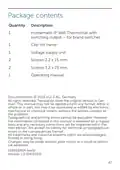
  • Page 46: Package contents include the Homematic IP Wall Thermostat with switching output, clip-on frame, voltage supply unit, and screws. The manual is a translation from the original version in German and may not be reproduced without written consent. Typographical and printing errors cannot be excluded, but the information is regularly reviewed for necessary corrections. No liability is accepted for technical or typographical errors or their consequences. All trademarks and industrial property rights are acknowledged. Changes may be made without prior notice due to technical advances. Documentation © 2023 eQ-3 AG, Germany. Printed in Hong Kong. Version 1.0 (04/2023).
  • Page 47: Information about this manual Hazard information Function and device overview General system information Start-up Installation instructions Operating modes and configuration Automatic mode Manual operation Holiday mode
  • Page 48: Selecting the desired temperature display. Configuring the floor heating actuator. Communication test. Operation. Troubleshooting. Command not confirmed. Duty cycle. Error codes and flashing sequences. Restore factory settings. Maintenance and cleaning. General information about radio operation. Technical specifications.
  • Page 49: Information about this manual Please read this manual carefully before beginning operation with your Homematic IP components. Keep the manual for future reference. If you hand over the device to others, please include this manual. Symbols used: Attention! This indicates a hazard. Please note: This section contains important additional information. Hazard information Do not open the device. It does not contain any parts that can be maintained by the user. In the event of an error, please have the device checked by an expert. For safety and licensing reasons (CE), unauthorized change and/or modification of the device is not permitted.
  • Page 50: Hazard information The device may only be operated in a dry and dust-free environment and must be protected from moisture, vibrations, solar or other methods of heat radiation, cold, and mechanical loads. The device is not a toy; do not allow children to play with it. Do not leave packaging material lying around as it can be dangerous in the hands of a child. We do not assume any liability for damage to property or personal injury caused by improper use or failure to observe the hazard information. The device may only be used for fixed installations and must be securely attached within a fixed installation. The actuator is part of the building installation. The relevant national standards and directives must be taken into consideration during planning and set-up. The device has been designed solely for operation on a 230 V/50 Hz AC supply. Only qualified electricians (to VDE 0100) are permitted to install the device.
  • Page 51: Hazard information Accident prevention regulations must be complied with while carrying out work on the 230 V mains. To avoid electric shocks, please disconnect the mains voltage. Non-compliance with installation instructions can cause fire or introduce other hazards. Take permissible cables and cable cross sections into account when connecting to the device terminals. Consider the technical data, including maximum permissible switching capacity and type of load, before connecting a load. All load data relates to ohmic loads. Do not exceed the capacity specified for the device. Exceeding this capacity could lead to destruction of the device, fires, or electric shocks. Before connecting the actuator, remove the fuse from the fuse box. The device has not been designed to support safety disconnection.
  • Page 52: Function and device overview The device may only be operated within residential buildings. Using the device for any purpose other than that described in this operating manual does not fall within the scope of intended use and shall invalidate any warranty or liability. The Homematic IP Wall Thermostat with switching output offers a relay output for controlling 230 V floor heating valve drives. By controlling the relay output, the room temperature is regulated according to your individually defined heating profiles. The Homematic IP Wall Thermostat can be used in connection with the Homematic IP Floor Heating Actuator or Homematic IP Radiator Thermostat for conventional radiators. The wall thermostat measures the temperature and humidity in the room and controls the relay output based on the current values. Controlling commands and configuration can be realized directly on the Homematic IP Wall Thermostat or comfortably via the free Homematic IP app.
  • Page 53: Function and device overview You can simply replace the existing wall thermostat of your installation by the Homematic IP Wall Thermostat and install the device in the flush-mounting box. Using the components of existing or planned switches and cabling reduces the installation costs to a minimum. The design, colour and finish of switches that have already been installed does not change, since existing frames can continue to be used. Device overview Clip-on frame Electronic unit (thermostat) Display System button (teach-in button and LED) Control wheel Voltage supply unit Display overview Set/actual temperature Humidity Warning about condensation Open window symbol
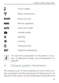
  • Page 54: General system information This device is part of the Homematic IP smart home system and works with the Homematic IP radio protocol. All devices of the system can be configured comfortably. Power supply Radio transmission Boost function Manual operation Automatic mode Holiday mode Heating Cooling Operating lock Setpoint temperature You will find a description of all symbols in section 6 Operating modes and configuration on page 63.
  • Page 55: Start-up You can operate the Homematic IP devices via the Central Control Unit CCU3 or in connection with various partner solutions. The available functions provided by the system in combination with other components are described in the Homematic IP User Guide. Please read this entire section before starting to install the device. Before installation, please note the device number (SGTIN) labelled on the device as well as the exact installation location. You can also find the device number on the QR code sticker supplied. Only to be installed by persons with the relevant electro-technical knowledge and experience. Incorrect installation can put your own life at risk and the lives of other users of the electrical system.
  • Page 56: Start-up Incorrect installation can lead to serious damage to property, such as fire. You may be personally liable for injuries or damage to property. Contact an electrical installer for assistance. Specialist knowledge is required for installation. The 5 safety rules include disconnecting from mains and safeguarding from switching on again. Evaluation of measuring results is essential. Selection of electrical installation material is necessary for safeguarding shut-off conditions. Understanding IP protection types is important. Installation should occur in accordance with DIN 49073-1. Hazard information must be observed during installation.
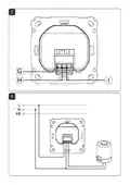
  • Page 57: Start-up Permitted cable cross sections for connecting to the wall thermostat are rigid cable and flexible cable with/without ferrule. To install the wall thermostat, please proceed as follows: Switch off the fuse of the power circuit. Remove the cover of your existing wall thermostat. To make removal easier, a flat, pointed object such as a slotted screwdriver can be used. Release the wiring and remove the existing wall thermostat. Connect the phase conductor to connecting terminal L of the voltage supply unit. Connect the neutral conductor to connecting terminal N of the voltage supply unit. Connect the conductor of the valve drive to connecting terminal 1 of the voltage supply unit.
  • Page 58: Start-up Place the voltage supply unit into the flush-mounted box and fix it using the supply screws. Place the frame of your installation and the supplied clip-on frame on the voltage supply unit. Place the electronic unit of the wall thermostat into the frame. Switch the fuse of the power circuit on again to activate the teach-in mode of the device. If the device has not yet been connected, teach-in mode will be activated during the first 3 minutes after the mains voltage has been switched on. During the first 10 minutes after the mains voltage has been switched on, the device remains in start mode. During this time, the relay is being triggered. During the following 20 minutes, the relay is operated via two-point control. If the temperature falls below the set-point temperature, the relay is switched on. After 20 minutes, the relay is operated via PI control with PWM output (normal operation).
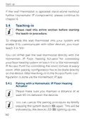
  • Page 59: Start-up If the wall thermostat is operated stand-alone, please continue to chapter 6. Teaching-in Please read this entire section before starting the teach-in procedure. To integrate the wall thermostat into your system, you must teach it in first. You can either pair the wall thermostat directly with the Homematic IP Floor Heating Actuator or teach it in to the Homematic IP Access Point. After pairing, configuration has to be done directly on the device. After teaching-in to the Access Point, configuration is done via the Homematic IP app. Pairing with a Homematic IP Floor Heating Actuator Please make sure you maintain a distance of at least 50 cm between the devices. You can cancel the pairing procedure by briefly pressing the system button again.
  • Page 60: Start-up If no teach-in operations are carried out, teach-in mode is exited automatically after 30 seconds. To pair the wall thermostat with a Homematic IP Floor Heating Actuator, the pairing mode of both devices has to be activated first. Select the required channel of the floor heating actuator and activate the pairing mode using a long button press. Press and hold down the system button of the wall thermostat for at least 4 seconds to activate the pairing mode. The device LED lights up green to indicate that teaching-in has been successful. If pairing failed, the device LED lights up red. Please try again. First set up your Homematic IP Access Point via the Homematic IP app to enable operation of other Homematic IP devices within your system.
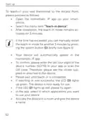
  • Page 61: Start-up To teach-in your wall thermostat to the Access Point, please proceed as follows: Open the Homematic IP app on your smartphone. Select the menu item Teach-in device. After installation, the teach-in mode remains activated for 3 minutes. If the time has exceeded, you can manually restart the teach-in mode for another 3 minutes by pressing the system button briefly. Your device will automatically appear in the Homematic IP app. To confirm, please enter the last four digits of the device number (SGTIN) in your app or scan the QR code. Please wait until teach-in is completed. If teaching-in was successful, the LED lights up green. The device is now ready for use. If the LED lights up red, please try again. In the app, select in which applications you want to use your device.
  • Page 62: Operating modes and configuration After teaching-in the wall thermostat to the Homematic IP Access Point, the menu of the wall thermostat will be hidden and settings can be adjusted only via the Homematic IP app. After installation (and teaching-in), you can individually adjust the settings to your personal needs via the configuration menu. Press and hold down the control wheel to open the configuration menu. Select the desired symbol by turning the control wheel and pressing it briefly if you want to adjust the settings of the following menu items. Press and hold down the control wheel to get back to the previous level. The menu automatically closes without applying changes if there is no operation for more than 1 minute. Automatic mode Manual operation Holiday mode Operating lock
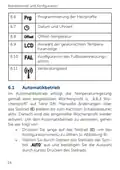
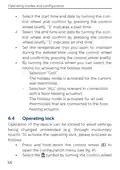
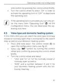
  • Page 63: Operating modes and configuration Valve type and domestic heating system Programming of heating profiles Date and time Offset temperature Selecting the desired temperature display Configuring the floor heating actuator Communication test Automatic mode In automatic mode, the temperature is controlled in accordance with the set week profile.
  • Page 64: Operating modes and configuration Manual operation In manual mode, the temperature is controlled in accordance with the current temperature set via the control wheel. The temperature remains activated until the next manual change. To activate the manual mode, press and hold down the control wheel to open the configuration menu. Select the symbol by turning the control wheel and confirm by pressing the control wheel briefly. Turn the control wheel to set the desired temperature. You can fully close/switch-off or open/switch-on the valve/relay by turning the control wheel as far as it will go in an anti-clockwise or clockwise direction. Holiday mode The holiday mode can be used if you want to maintain a fixed temperature for a certain period. To activate the holiday mode, press and hold down the control wheel to open the configuration menu. Select the symbol by turning the control wheel and confirm by pressing the control wheel briefly.
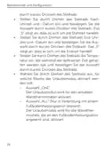
  • Page 65: Operating modes and configuration Select the start time and date by turning the control wheel and confirm by pressing the control wheel briefly. “S” indicates a start time. Select the end time and date by turning the control wheel and confirm by pressing the control wheel briefly. “E” indicates an end time. Set the temperature that you want to maintain during the defined time using the control wheel and confirm by pressing the control wheel briefly. By turning the control wheel you can select the rooms for activating the holiday mode. Selection “OnE”: The holiday mode is activated for the current wall thermostat. Selection “ALL”: The holiday mode is activated for all wall thermostats that are connected to the floor heating actuator. Operating lock Operation of the device can be locked to avoid settings being changed unintentionally. To activate the operating lock, please proceed as follows: Press and hold down the control wheel to open the configuration menu.
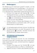
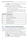
  • Page 66: Operating modes and configuration Turn the control wheel to select “On” in order to activate the operating lock or “OFF” to deactivate the operating lock. If the operating lock is activated you can only enter the menu item “Operating lock” via the configuration menu. In this menu item you can select the valve type (normally closed or normally open) that is connected to the switch relay as well as your domestic heating system. Press and hold down the control wheel to open the configuration menu. Select the symbol by turning the control wheel and confirm by pressing the control wheel briefly. Turn the control wheel and select “Unit” and “nc” or “no” for normally closed or normally open as well as “ArEA” and a number between 0 and 4 for your domestic heating system.
  • Page 67: Operating modes and configuration Standard floor heating Low energy floor heating Radiator Passive convector Active convector Programming the week profiles You can use this menu item for configuring heating and cooling profiles and to adjust the week profiles according to your personal needs. Press and hold down the control wheel to open the configuration menu. Select the symbol by turning the control wheel and confirm by pressing the control wheel briefly.
  • Page 68: Operating modes and configuration You can use your floor heating system to heat rooms during winter or to cool rooms during summer. Select “HEAT” for heating and “COOL” for cooling in the menu item “type” by turning the control wheel and confirm by pressing the control wheel briefly. You can select between the following 6 pre-configured profiles. Select the number of the required profile in the menu item “Pr.nr.” by turning the control wheel and confirm by pressing the control wheel briefly. If the selected profile is a heating profile, the room is heated as soon as the temperature falls below the defined value. If the selected profile is a cooling profile, the room is cooled as soon as the temperature increases above the defined value. After switching from “heating” to “cooling” in the menu, the profiles are changed automatically.
  • Page 69: Operating modes and configuration Profile 1 Pre-configured heating via radiator thermostat Monday to Friday schedule with specified temperature settings. Profile 2 Pre-configured heating via floor heating Monday to Friday schedule with specified temperature settings.
  • Page 70: Operating modes and configuration Profile 3 Alternative profile Profile 4 Alternative cooling profile 1 Temperature settings for different time slots Monday to Friday schedule Saturday to Sunday schedule Temperature adjustments throughout the day Different profiles for varying needs
  • Page 71: Operating modes and configuration Profile 5 Pre-configured cooling via floor heating Monday to Friday Temperature settings for different time slots Saturday to Sunday Temperature settings for different time slots Profile 6 Alternative cooling profile 1 Temperature settings for different time slots
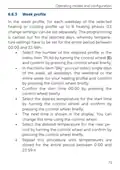
  • Page 72: Operating modes and configuration In the week profile, for each weekday of the selected heating or cooling profile, up to 6 heating phases can be set separately. The programming is carried out for the selected days, whereby temperature settings have to be set for the entire period between 00:00 and 23:59h. Select the number of the required profile in the menu item “Pr.Ad” by turning the control wheel and confirm by pressing the control wheel briefly. In the menu item “dAy” you can select single days of the week, all weekdays, the weekend or the entire week for your heating profile. Confirm the start time 00:00 by pressing the control wheel briefly. Select the desired temperature for the start time by turning the control wheel and confirm by pressing the control wheel briefly. The next time is shown in the display. You can change this time using the control wheel. Select the desired temperature for the next period by turning the control wheel and confirm by pressing the control wheel briefly. Repeat this procedure until temperatures are stored for the entire period between 0:00 and 23:59 h.
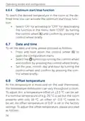
  • Page 73: Operating modes and configuration Optimum start/stop function To reach the desired temperature in the room at the defined time, you can activate the optimum start/stop function. Select “On” for activating or “OFF” for deactivating the function in the menu item “OSSF” by turning the control wheel and confirm by pressing the control wheel briefly. Date and time To set the date and time, please proceed as follows: Press and hold down the control wheel to open the configuration menu. Select the symbol by turning the control wheel and confirm by pressing the control wheel briefly. Set the year, month, day, and hour by turning the control wheel and confirm by pressing the control wheel briefly. Offset temperature As the temperature is measured on the wall thermostat, the temperature distribution can vary throughout a room. To adjust this, a temperature offset of 3.5 °C can be set. If a nominal temperature of e.g. 20 °C is set but the room presents with only 18 °C, an offset of -2.0 °C needs to be set. An offset temperature of 0.0° is set in the factory settings.
  • Page 74: Operating modes and configuration Press and hold down the control wheel to open the configuration menu. Select the symbol by turning the control wheel and confirm by pressing the control wheel briefly. Turn the control wheel until the desired temperature appears (3.5 °C maximum). Confirm by pressing the control wheel briefly. You can adjust the temperature to be displayed. You can also define whether the humidity value shall be displayed or not. Select the symbol by turning the control wheel and confirm by pressing the control wheel briefly. Turn the control wheel and select options for displaying temperature and humidity. You can use this menu item for configuring your HomeMatic IP Floor Heating Actuator.
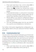
  • Page 75: Operating modes and configuration Press and hold down the control wheel to open the configuration menu. Select the symbol by turning the control wheel and confirm by pressing the control wheel briefly. If the wall thermostat is connected to more than one floor heating actuator, please select the required floor heating using the control wheel. Please define if you want to configure the device parameters or the channel parameters. You can individually adjust the line-up time/follow-up time, eco temperatures, intervals, etc. For further information regarding the configuration options, please refer to the user manual of the floor heating actuator. Communication test You can check the connection between your Homematic IP Wall Thermostat and the Homematic IP Floor Heating Actuator. During this test, the wall thermostat transmits a switching command to the floor heating actuator. Depending on the current status of the actuator, the device is switched on or off for confirmation after receiving the command.
  • Page 76: Operation Select the symbol by turning the control wheel and confirm by pressing the control wheel briefly. After configuration, simple operations are available directly on the device. If the wall thermostat is in standby mode, please press the control wheel once before operation to activate the device. Temperature: Turn the control wheel of the wall thermostat to manually change the temperature. In automatic mode, the manually set temperature will remain the same until the next point at which the profile changes. During manual operation, the temperature remains activated until the next manual change. Boost function for Homematic IP Radiator Thermostats: Press the control wheel of the wall thermostat briefly to activate the boost function for heating up the radiator quickly. There will be a pleasant room temperature right away because of the radiated heat.
  • Page 77: Troubleshooting The boost function can only be executed in connection with a Homematic IP Radiator Thermostat. If at least one receiver does not confirm a command, the device LED lights up red at the end of the failed transmission process. The failed transmission may be caused by radio interference. Receiver cannot be reached. Receiver is unable to execute the command (load failure, mechanical blockade, etc.). Receiver is defective. The duty cycle is a legally regulated limit of the transmission time of devices in the 868 MHz range. The aim of this regulation is to safeguard the operation of all devices working in the 868 MHz range. The maximum transmission time of any device is 1% of an hour (i.e. 36 seconds in an hour). Homematic IP devices are designed and produced with 100% conformity to this regulation.
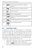
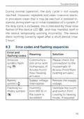
  • Page 78: Troubleshooting During normal operation, the duty cycle is not usually reached. However, repeated and radio-intensive teach-in processes may lead to it being reached in isolated instances during start-up or initial installation of a system. If the duty cycle is exceeded, this is indicated by three slow flashes of the device LED and may manifest itself in the device temporarily working incorrectly. The device starts working correctly again after a short period (max. 1 hour). Error codes and flashing sequences Antenna symbol flash indicates a communication error with Homematic IP Access Point/floor heating actuator. Battery symbol indicates that the supply voltage is interrupted. Flashing humidity symbol indicates that the humidity limit (60%) in the room is exceeded. Solutions include checking the connection to the Homematic IP Access Point/floor heating actuator, restoring the supply voltage, and ventilating the room.
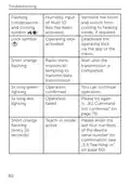
  • Page 79: Troubleshooting Flashing condensation and cooling Humidity input of Multi IO Box has been activated Ventilate the room and switch from cooling to heating mode, if required Lock symbol Operating lock activated Deactivate the operating lock via the app or the menu Short orange flashing indicates radio transmission/attempting to transmit/data transmission Operation confirmed Operation failed, please try again Teach-in mode requires confirmation of the last four numbers of the device serial number
  • Page 80: Restore factory settings The factory settings of the device can be restored. If you do this, you will lose all your settings. To restore the factory settings of the wall thermostat, please proceed as follows: Pull the electronic unit forward. Place the electronic unit back on the voltage supply unit and press and hold down the system. Transmission failed or duty cycle limit is reached. Please try again (see sec. 8.1 Command not confirmed on page 78 or 8.2 Duty cycle on page 78). Device defective. Please see your app for error message or contact your retailer. Test display. After the test display has stopped, you can continue.
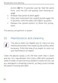
  • Page 81: Maintenance and cleaning The device does not require you to carry out any maintenance other than replacing the battery when necessary. Enlist the help of an expert to carry out any maintenance or repairs. Clean the device using a soft, lint-free cloth that is clean and dry. You may dampen the cloth a little with lukewarm water in order to remove more stubborn marks. Do not use any detergents containing solvents, as they could corrode the plastic housing and label.
  • Page 82: General information about radio operation Radio transmission is performed on a non-exclusive transmission path, which means that there is a possibility of interference occurring. Interference can also be caused by switching operations, electrical motors or defective electrical devices. The range of transmission within buildings can differ greatly from that available in the open air. Environmental factors such as humidity in the vicinity have an important role to play, as do on-site structural/screening conditions. eQ-3 AG declares that the radio equipment type Homematic IP HmIP-BWTH-A is in compliance with Directive 2014/53/EU.
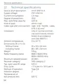
  • Page 83: Device short description: HmIP-BWTH-A Supply voltage: 230 V/50 Hz Current consumption: 1 A max. Degree of protection: IP20 Max. switching capacity: 230 W Kind of load: ohmic load Installation: only in normal commercial switch boxes in accordance with DIN 49073-1. Ambient temperature: 0 to 50 °C Dimensions (W x H x D): 55 x 55 x 54 mm (without frame), 86 x 86 x 54 mm (including frame) Weight: 136 g
  • Page 84: Technical specifications Withstand voltage: 4000 V Construction of the regulation and control device: independently mounted electronic regulation and control device Subject to technical changes. Instructions for disposal Do not dispose of the device with regular domestic waste. Electronic equipment must be disposed of at local collection points for waste electronic equipment in compliance with the Waste Electrical and Electronic Equipment Directive. Information about conformity The CE sign is a free trading sign addressed exclusively to the authorities and does not include any warranty of any properties. For technical support, please contact your retailer.
  • Page 85: Free download of the Homematic IP app! Manufacturer’s authorised representative: eQ-3 AG