Honeywell RTHL3550 Non-programmable Thermostat Installation Guide


Quick Installation Guide
RTHL3550
Non-programmable Thermostat
69-2584ES-01
firealarmresources.com

| General | Details |
|---|---|
| Name | Honeywell RTHL3550 Non-programmable Thermostat Installation Guide |
| Make | Honeywell |
| Language | English |
| Filetype | PDF (Download) |
| File size | 0.72 MB |


Honeywell T6 Pro Programmable Thermostat User Manual

Honeywell D1-528 Direct Thermostat Installation Guide

Honeywell FocusPRO P200 Programmable Thermostat User Guide

Honeywell RCHT8610WF Series Smart Thermostat Installation Guide

Honeywell T9 Smart Thermostat Installation Guide

Honeywell TH2320WF4011 FocusPRO Smart S200 Series Thermostat User Guide

Honeywell TL116A Thermostat Installation Guide

T10 Pro Smart Thermostat with Redlink Room Sensor

Honeywell TH6320WF2003 Lyric T6 Pro Wi-Fi Programmable Thermostat User Guide

Honeywell Lyric T5 Wi-Fi Thermostat Installation Guide

Honeywell RTHL3550 Non-programmable Thermostat Installation Guide Overview
Summary of Contents
- Page 1: Quick installation guide Non-programmable thermostat
- Page 2: Installation is easy. Label wires and remove your old thermostat. Install and wire your new thermostat. Set your new thermostat to match your heating/cooling system. It is preset for the most common system. We are here to help. Call for wiring assistance before returning the thermostat to the store.
- Page 3: Turn off power to heating/cooling system.
- Page 4: Remove old thermostat but leave wallplate with wires attached. Is there a sealed tube containing mercury? Do not place your old thermostat in the trash if it contains mercury in a sealed tube. Contact the Thermostat Recycling Corporation for information on how and where to properly and safely dispose of your old thermostat.
- Page 5: Label the wires using the supplied wire labels as you disconnect them. Note if a jumper wire was used on the old thermostat and review in the wiring section.
- Page 6: Separate wallplate from new thermostat. Remove battery holder. Pull here to remove wallplate from new thermostat.
- Page 7: Mount the new wallplate using the included screws and anchors. Drill 3/32-in. holes for plaster. Drill 3/16-in. holes for drywall. Use hammer to tap the anchors into the wall.
- Page 8: Connect wires by matching wire labels. Remove the metal jumper if both R and Rc wires are present. Refer to page 24 if the labels do not match. For heat pump systems, see pages 25-26. Assistance is available for wiring issues.
- Page 9: Install two AA alkaline batteries. Back of thermostat.
- Page 10: Install thermostat onto the wallplate on the wall.
- Page 11: Turn the power back on to the heating/cooling system.
- Page 12: If your system type is: Single stage heat and cool Congratulations, you’re done! If your system type is: Multistage heat and cool Heat pump without backup heat Heat pump with backup heat Heat only Cool only Continue with advanced installation on page 12 to match your thermostat to your system type. This thermostat works on 24 volt or 750 mV systems. It will NOT work on multi-stage heat pump systems or 120/240 volt systems.
- Page 13: Advanced installation System setup Wiring Troubleshooting Customer assistance Limited warranty
- Page 14: Advanced installation guide System setup Press and hold the s and FAN buttons until the screen changes (approximately 5 seconds). Press s or t to change settings. Press DONE to exit. Press NEXT to advance to next function.
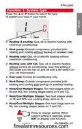
- Page 15: Function 1: System type Press the s or t button to select the type of system you have in your home. Heating & cooling: Gas, oil or electric heating with central air conditioning. Heat pump: Outside compressor provides both heating and cooling without backup or auxiliary heat. Heating only: Gas, oil or electric heating without central air conditioning. Heating only with fan: Gas, oil or electric heating without central air conditioning. Cool only: Central air conditioning only. Heat pump: Outside compressor provides both heating and cooling with backup or auxiliary heating. Heat/cool multiple stages: Two heat stages, two cooling stages. Heat/cool multiple stages: Two heat stages, one cooling stage. Heat/cool multiple stages: One heat stage, two cooling stages.
- Page 16: Advanced installation guide Press the s or t button to select whether your changeover valve is used in heating or cooling. If Function 2 does not appear, please turn to the next page to continue. Cooling changeover valve: Use this setting if you connected a wire labeled “O” to the O/B wire terminal. Heating changeover valve: Use this setting if you connected a wire labeled “B” to the O/B wire terminal. Press to change setting. When correct setting is selected, press NEXT to display next function.
- Page 17: Press the s or t button to select your heating system and fan operation. If Function 3 does not appear, please turn to the next page to continue. Use this setting if you have a gas or oil heating system. Use this setting if you have an electric heating system. Thermostat controls fan operation for electric heat. Press to change setting. When correct setting is selected, press NEXT to display next function.
- Page 18: Advanced installation guide Press the s or t button to select your heating system and optimize its operation. If function 5 does not appear, please turn to the next page to continue. Gas or oil furnace: Use this setting if you have a standard gas or oil furnace that is less than 90% efficient. Electric furnace: Use this setting if you have any type of electric heating system. Hot water or high-efficiency furnace: Use this setting if you have a hot water system or a gas furnace of greater than 90% efficiency. Gas/oil steam or gravity system: Use this setting if you have a steam or gravity heat system. Press to change setting. When the correct setting is selected, press NEXT to display the next function.
- Page 19: Function 6: Stage 2 heat cycle rate Press the s or t button to select your heating system and optimize its operation. If Function 6 does not appear, please turn to the next page to continue. Gas or oil furnace: Use this setting if you have a standard gas or oil furnace that is less than 90% efficient. Electric furnace: Use this setting if you have any type of electric heating system. Hot water or high-efficiency furnace: Use this setting if you have a hot water system or a gas furnace of greater than 90% efficiency. Gas/oil steam or gravity system: Use this setting if you have a steam or gravity heat system. Press to change setting. When correct setting is selected, press NEXT to display next function.
- Page 20: Advanced installation guide Function 8: Emergency heat cycle rate Press the s or t button to select your heating system and optimize its operation. If Function 8 does not appear, please turn to the next page to continue. Electric furnace: Use this setting if you have any type of electric heating system. Gas/oil steam or gravity system: Use this setting if you have a steam or gravity heat system. Hot water or high-efficiency furnace: Use this setting if you have a hot water system or a gas furnace of greater than 90% efficiency. Gas or oil furnace: Use this setting if you have a standard gas or oil furnace that is less than 90% efficient. Press to change setting. When correct setting is selected, press NEXT to display next function.
- Page 21: Changeover Press the s or t button to select Manual or Auto. Manual Changeover: (Heat/Off/Cool) Automatic Changeover: (Heat/Off/Cool/Auto) Automatically turns on heat or cool based on room temperatures. Caution: To avoid possible compressor damage, set to option 0 if the outside temperature drops below 50 ºF (10 ºC). Note: System maintains a minimum 3 ºF difference between heat and cool settings. Press to change setting. When correct setting is selected, press NEXT to display next function.
- Page 22: Advanced installation guide Press the s or t button to select Fahrenheit or Celsius temperature display. Fahrenheit temperature display (°F). Celsius temperature display (°C). Press to change setting. When correct setting is selected, press NEXT to display next function.
- Page 23: Maximum heat temperature setting (°F); (4.5°C to 31.5°C). Press the s or t button to select maximum heat temperature setting. Press to change setting. When correct setting is selected, press NEXT to display next function.
- Page 24: Advanced installation guide Minimum cool temperature setting (°F); (10.5°C to 37°C) Press to change setting. When correct setting is selected, press done to exit and save changes. Congratulations, you’re done!
- Page 25: Wiring—Conventional System If labels do not match letters on the thermostat, check the chart below and connect to terminal as shown here. If wires will be connected to both R and Rc terminals, remove metal jumper. Do not use C, X or B. Wrap bare end of wire with electrical tape.
- Page 26: Advanced installation guide Connect wires: Heat pump Match each labeled wire with the same letter on the new thermostat. Use a screwdriver to loosen screws, insert wires into the hole under the screw, then tighten screws until the wire is secure. If E and Aux do not each have a wire connected, use a small piece of wire to connect them to each other. Push any excess wire back into the wall opening. Labels don’t match? See page 26. Wiring complete, return to Step 7.
- Page 27: Alternate wiring (for heat pumps only) If labels do not match letters on the thermostat, check the chart below and connect to terminal as shown here. Leave metal jumper in place, connecting R & Rc terminals. If your old thermostat had both V and VR wires, stop now and contact a qualified contractor for help. If your old thermostat had separate O and B wires, wrap the B wire in electrical tape and do not connect. If your old thermostat had Y1, W1 and W2 wires, stop now and contact a qualified contractor for help. If E and Aux terminals do not each have a wire connected, use a small piece of wire to connect them to each other. Wiring complete, return to Step 7.
- Page 28: Advanced installation guide Troubleshooting If you have difficulty with your thermostat, please try the following suggestions. Most problems can be corrected quickly and easily. Make sure fresh AA alkaline batteries are correctly installed. Display is blank. Make sure heating and cooling temperatures are set to acceptable ranges. Temperature settings do not change. Check Function 1: System Type to make sure it is set to match your heating and cooling equipment. Cannot change system setting to Cool. Check Function 3: Heating Fan Control to make sure it is set to match your heating equipment. Fan does not turn on when heat is required.
- Page 29: Troubleshooting heating or cooling system does not respond. Press SYSTEM button to set system to Heat and ensure the temperature is set higher than the inside temperature. Press SYSTEM button to set system to Cool and ensure the temperature is set lower than the inside temperature. Check circuit breaker and reset if necessary. Make sure power switch at heating and cooling system is on. Ensure furnace door is closed securely. Wait 5 minutes for the system to respond. Compressor protection feature is engaged; wait 5 minutes for the system to restart safely. Check Function 2: Heat Pump Changeover Valve to ensure proper configuration. Check Function 1: System Type to ensure it matches your heating and cooling equipment.
- Page 30: Advanced installation guide For assistance with this product, please visit yourhome.honeywell.com or call Honeywell Customer Care toll-free. To save time, please remove the battery holder and note your model number and date code before calling. To order accessories or replacement parts, please call Honeywell Customer Care toll-free. Battery holder - Part No. 50007072-001 Cover plate assembly - Part No. 50002883-001 Use the cover plate assembly to cover marks left by old thermostats.
- Page 31: Honeywell warrants this product, excluding battery, to be free from defects in workmanship or materials, under normal use and service, for a period of one year from the date of purchase. If the product is determined to be defective or malfunctions during the warranty period, Honeywell shall repair or replace it at their option. To claim the warranty, return the product with proof of purchase to the place of purchase or contact Honeywell Customer Care. This warranty does not cover removal or reinstallation costs. The warranty is void if the defect or malfunction was caused by damage while in the consumer's possession. Honeywell is not liable for any loss or damage of any kind, including incidental or consequential damages. This warranty is the only express warranty Honeywell makes on this product. The duration of any implied warranties is limited to the one-year duration of this warranty. Some states do not allow limitations on how long an implied warranty lasts, so the limitation may not apply to you. This warranty gives you specific legal rights, and you may have other rights which vary from state to state.
- Page 32: Do not place your old thermostat in the trash if it contains mercury in a sealed tube. Contact the Thermostat Recycling Corporation for information on how and where to properly and safely dispose of your old thermostat. To avoid possible compressor damage, do not run air conditioner if the outside temperature drops below 50 °F (10 °C). Automation and Control Solutions. Honeywell International Inc. Honeywell Limited-Honeywell Limitée. U.S. Registered Trademark. © 2011 Honeywell International Inc. Printed in the U.S.
- Page 33: Guía de instalación rápida Termostato no programable
- Page 34: La instalación es fácil. Rotule los cables y retire el termostato viejo. Instale y conecte los cables de su nuevo termostato. Ajuste su nuevo termostato para que concuerde con su sistema de calefacción/refrigeración. Está preconfigurado para el sistema más común. Esta guía está aquí para ayudarle. Llame para obtener asistencia con el cableado antes de devolver el termostato a la tienda.
- Page 35: Desconecte la alimentación en el sistema de calefacción/refrigeración.
- Page 36: Remueva su viejo termostato. Retire el termostato existente pero deje la placa de pared con los cables adheridos. ¿Hay un tubo sellado que contiene mercurio? Deje la placa de pared en su lugar. AVISO DE MERCURIO: No arroje su viejo termostato a la basura si contiene mercurio en un tubo sellado. Consulte en la cubierta de este manual las instrucciones para su desecho apropiado. Contacte a la Thermostat Recycling Corporation para información sobre cómo y dónde desechar su viejo termostato de manera segura.
- Page 37: Identifique los cables a medida que los desconecta, utilizando las etiquetas que se suministran. Rótulos para los cables. ¿Cable de puente utilizado en el termostato usado? En caso afirmativo, escriba cuáles letras conecta el puente y revise en la sección de cableado.
- Page 38: Separe la placa de pared del termostato nuevo. Quite el soporte de la batería. Hale de aquí para quitar la placa de pared del nuevo termostato. Placa de pared.
- Page 39: Monte la nueva placa de pared utilizando los tornillos y anclajes que se suministran. Taladre agujeros de 3/32 in. (2,4 mm) en yeso. Taladre agujeros de 3/16 in. (4,8 mm) en paneles de yeso. Utilice un martillo para golpear ligeramente los anclajes en la pared.
- Page 40: Conecte los cables. Simplemente haga corresponder las etiquetas de los cables. Retire el empalme metálico si tiene los cables “R” y “Rc”. ¿Los rótulos no coinciden? Ver página 23. ¿Tiene un sistema de bomba de calor? Ver página 24-25. Estamos aquí para ayudarle. Llame para asistencia con el cableado.
- Page 41: Instale las baterías. Instale dos baterías alcalinas AA en la parte de atrás del termostato. Parte de atrás del termostato.
- Page 42: Instale el termostato en la placa de pared sobre la pared.
- Page 43: Active nuevamente el suministro eléctrico del sistema de calefacción/refrigeración.
- Page 44: Si su tipo de sistema es: Calor y frío de una sola etapa. Calefacción y refrigeración de etapas múltiples. Bomba de calor sin calor de respaldo. Bomba de calor con calor de respaldo. Calefacción únicamente. Refrigeración únicamente. Continúe con la instalación avanzada en la página 13. Este termostato funciona con sistemas de 24 voltios o 750 mV. No funciona con sistemas de bomba de calor de etapas múltiples ni con sistemas de 120/240 voltios.
- Page 45: Guía de instalación avanzada Cómo cambiar la configuración Cableado En caso de dificultades Asistencia al cliente Garantía limitada
- Page 46: Guía de instalación avanzada Pulse y mantenga presionados los botones s y “FAN” para introducir la configuración del sistema. Presione s o t para cambiar la configuración. Presione “NEXT” para avanzar a la siguiente función. Presione “DONE” para salir y guardar la configuración.
- Page 47: Función 1: Tipo de sistema Presione los botones s o t para seleccionar el tipo de sistema de su hogar. Calefacción y refrigeración: Sistema de calefacción a gas, a aceite o eléctrico con aire acondicionado. Bomba de calor: El compresor externo proporciona tanto calefacción como refrigeración sin calefacción de respaldo o auxiliar. Calefacción únicamente: Sistema de calefacción a gas, a aceite o eléctrico sin aire acondicionado central. Calefacción únicamente con ventilador: Sistema de calefacción a gas, a aceite o eléctrico sin aire acondicionado central. Refrigeración únicamente: Aire acondicionado central únicamente. Etapas múltiples de calefacción/refrigeración: Dos etapas de calefacción, dos etapas de refrigeración. Etapas múltiples de calefacción/refrigeración: Dos etapas de calefacción, una etapa de refrigeración. Etapas múltiples de calefacción/refrigeración: Una etapa de calefacción, dos etapas de refrigeración. Presione para cambiar la configuración.
- Page 48: Guía de instalación avanzada Función 2: Válvula inversora de la bomba de calor Presione los botones s o t para seleccionar el uso de la válvula inversora para calefacción o refrigeración. Nota: Si no aparece la función 2, pase a la página siguiente para continuar. Válvula inversora de refrigeración: Use esta configuración si conectó un cable con la etiqueta “O” a un terminal de cable O/B. Válvula inversora de calefacción: Use esta configuración si conectó un cable con la etiqueta “B” a un terminal de cable O/B. Presione para cambiar la configuración. Una vez seleccionada la configuración correcta, presione “NEXT” para visualizar la nueva función.
- Page 49: Función 3: Control del ventilador para calefacción Presione los botones s o t para seleccionar el sistema de calefacción y el modo de funcionamiento del ventilador. Si no aparece la función 3, pase a la página siguiente para continuar. Sistemas de calefacción a gas o a aceite: Use esta configuración si tiene un sistema de calefacción a gas o a aceite. Sistema de calefacción eléctrico: Use esta configuración si tiene un sistema de calefacción eléctrico. El termostato controla el modo de funcionamiento del ventilador. Presione para cambiar la configuración. Una vez seleccionada la configuración correcta, presione “NEXT” para visualizar la nueva función.
- Page 50: Guía de instalación avanzada Función 5: Velocidad del ciclo térmico Use esta configuración si tiene un sistema de calefacción a gas o a aceite estándar de menos de un 90% de efectividad. Use esta configuración si tiene cualquier sistema de calefacción eléctrico. Use esta configuración si tiene un sistema de calefacción de agua caliente o un sistema de calefacción a gas con más del 90% de efectividad. Use esta configuración si tiene un sistema de calefacción de vapor o gravedad. Presione para cambiar la configuración. Una vez seleccionada la configuración correcta, presione “NEXT” para visualizar la nueva función.
- Page 51: Función 6: Índice del ciclo de calefacción en la etapa 2 Use esta configuración si tiene un sistema de calefacción a gas o a aceite estándar de menos de un 90% de efectividad. Use esta configuración si tiene cualquier sistema de calefacción eléctrico. Use esta configuración si tiene un sistema de calefacción de agua caliente o un sistema de calefacción a gas con más del 90% de efectividad. Use esta configuración si tiene un sistema de calefacción de vapor o gravedad. Presione para cambiar la configuración. Una vez seleccionada la configuración correcta, presione “NEXT” para visualizar la nueva función.
- Page 52: Guía de instalación avanzada Función 8: Índice del ciclo de calefacción de emergencia Presione los botones para seleccionar el sistema de calefacción y optimizar la operación. Si no aparece la función 8, pase a la página siguiente para continuar. Sistema de calefacción eléctrico: Use esta configuración si tiene cualquier sistema de calefacción eléctrico. Sistemas de vapor o de gravedad a gas o a aceite: Use esta configuración si tiene un sistema de calefacción de vapor o gravedad. Sistema de calefacción de agua caliente o de alta efectividad: Use esta configuración si tiene un sistema de calefacción de agua caliente o un sistema de calefacción a gas con más del 90% de efectividad. Sistemas de calefacción a gas o a aceite: Use esta configuración si tiene un sistema de calefacción a gas o a aceite estándar de menos de un 90% de efectividad. Presione para cambiar la configuración. Una vez seleccionada la configuración correcta, presione “NEXT” para visualizar la nueva función.
- Page 53: Function 12: Cambio manual/automático Presione los botones s o t para seleccionar el cambio manual o automático. Cambio manual: (Calefacción/Apagado/ Enfriamiento) Cambio automático: (Calefacción/Apagado/ Enfriamiento/Automático) Activa automáticamente la calefacción o el enfriamiento basado en las temperaturas de la habitación. Precaución: Para evitar posibles daños al compresor, coloque la opción 0 si la temperatura externa es inferior a 50ºF (10ºC). Nota: El sistema mantiene un mínimo de 3ºF entre las configuraciones de calefacción y enfriamiento. Presione para cambiar la configuración. Una vez seleccionada la configuración correcta, presione “NEXT” para visualizar la nueva función.
- Page 54: Guía de instalación avanzada Función 14: Visor de la temperatura About your new thermostat Presione los botones s o t para optar entre visualizar la temperatura en grados Fahrenheit o en grados Celsius. Visualización de la temperatura en Celsius (°C) Presione para cambiar la configuración. Una vez seleccionada la configuración correcta, presione “NEXT” para visualizar la nueva función.
- Page 55: Función 27: máxima de temperatura Presione los botones s o t para optar entre máxima de temperatura. La configuración máxima de temperatura (°F); (4.5°C to 31.5°C). Presione para cambiar la configuración. Una vez seleccionada la configuración correcta, presione “NEXT” para visualizar la nueva función.
- Page 56: Guía de instalación avanzada Función 28: mínima de enfriamiento La configuración mínima de enfriamiento (°F); (10,5°C to 37°C) Presione para cambiar la configuración. Cuando haya seleccionado la configuración correcta, presione “DONE” para salir y guardar los cambios. ¡Felicitaciones, ya terminó!
- Page 57: Si las etiquetas no coinciden con las letras del termostato, controle el cuadro de la derecha y conecte el terminal como se ilustra aquí. En caso de conectar los cables tanto al terminal R como al Rc, quite el puente metálico. No use los cables C, X ni B. Coloque cinta aisladora en los extremos desnudos del cable.
- Page 58: Guía de instalación avanzada Conecte los cables: Bomba de calor Coordine cada cable etiquetado con la misma letra del termostato nuevo. Con un destornillador afloje los tornillos de los terminales, inserte los cables, luego ajuste los tornillos. Si E y Aux no tienen un cable conectado cada uno, utilice una pequeña pieza de cable para conectarlos uno con otro. Introduzca el excedente de cable en la abertura de la pared. ¿Los rótulos no coinciden? Consulte la página 26. El cableado está completo, regrese al paso 8.
- Page 59: Cableado alternativo (para bombas de calor únicamente) Si las etiquetas no coinciden con las letras del termostato, controle el cuadro de la derecha y conecte el terminal como se ilustra aquí. Deje el empalme en lugar, entre terminales de R y Rc. Si su termóstato existente tenía cables V y VR, ahora pare y entre en contacto con un contratista para la ayuda. Si su termostato existente tenía cables O y B separados, envuelva el cable B en cinta aislante y no lo conecte. Si su termostato existente tenía cables Y1, W1 y W2, ahora pare y entre en contacto con un contratista para la ayuda. Si E y los terminales Aux no tienen cada uno un cable conectado, utilice un pedazo pequeño de cable para conectarlos el uno al otro. El cableado está completo, regrese al paso 8.
- Page 60: Guía de instalación avanzada Si usted tiene dificultades con su termostato, pruebe las sugerencias que figuran a continuación. Asegúrese de que las baterías AA alcalinas estén instaladas correctamente. Asegúrese de que las temperaturas de calor y frío estén configuradas en rangos aceptables. Calor: De 40 °F a 90 °F (de 4,5 °C a 32 °C). Frío: De 50 °F a 99 °F (de 10 °C a 37 °C). Controle la función 1 (Tipo de sistema) para asegurarse de que coincida con el equipo de calefacción y refrigeración. Controle la función 3 (Control del ventilador para calefacción) para asegurarse de que coincida con el equipo de calefacción y refrigeración. Sujete y quite el termostato de la placa para pared. Controle que los cables desnudos no se toquen entre sí.
- Page 61: El sistema Presione el botón “SYSTEM” para configurar el sistema en “Heat”. Asegúrese de que la temperatura sea más alta que la temperatura interna. Presione el botón “SYSTEM” para configurar el sistema en “Cool”. Asegúrese de que la temperatura sea más baja que la temperatura interna. Controle el interruptor de circuito y, si es necesario, reinícielo. Asegúrese de que el interruptor de energía del sistema de calefacción y enfriamiento esté encendido. Asegúrese de que la puerta del sistema de calefacción esté bien cerrada. Espere 5 minutos para que responda el sistema. La función de la protección del compresor está funcionando. Controle la función 2 (Válvula inversora de la bomba de calor) para asegurarse de que esté correctamente configurada en su sistema. La bomba de calor emite aire frío en el modo de calor o aire caliente en el modo de frío. Controle la función 1 (Tipo de sistema) para asegurarse de que coincida con el equipo de calefacción y refrigeración.
- Page 62: Guía de instalación avanzada Ayuda al cliente Para obtener asistencia relacionada con este producto, visite el sitio web o comuníquese con el número gratuito de Atención al cliente de Honeywell. Para ahorrar tiempo, anote el número de modelo y el código de fecha antes de llamar. Accesorios y piezas de repuesto Soporte de la batería - Part No. 50007072-001 Ensamblado de la placa de cubierta - Part No. 50002883-001 Honeywell garantiza este producto, a excepción de la batería, por el término de un (1) año contra cualquier defecto de fabricación o de los materiales. Si en cualquier momento durante el período de garantía se verifica que el producto tiene un defecto o que funciona mal, Honeywell lo reparará o reemplazará. Si el producto tiene defectos, devuélvalo con la factura de venta u otra prueba de compra fechada, al lugar donde lo compró.
- Page 63: Devolución de mercaderías de Honeywell. Esta garantía no cubre los costos de extracción o reinstalación. La única responsabilidad de Honeywell será reparar o reemplazar el producto. Honeywell no responderá por la pérdida o daño de ningún tipo. Algunos estados no permiten la exclusión o limitación del daño incidental o indirecto. La presente garantía es la única garantía expresa que Honeywell proporciona. La duración de las garantías implícitas está limitada a la duración de un año. Esta garantía le brinda derechos legales específicos. Si tiene preguntas sobre la presente garantía, sírvase escribir a Honeywell Customer Relations. En Canadá, escriba a Retail Products ON15-02H, Honeywell Limited.
- Page 64: Aviso de mercurio: No arroje su viejo termostato a la basura si contiene mercurio en un tubo sellado. Contact the Thermostat Recycling Corporation for information on how and where to properly and safely dispose of your old thermostat. Precaución: Para evitar posibles daños al compresor, no utilice el aire acondicionado si la temperatura externa es inferior a 50 ºF (10 ºC). Soluciones para automatización y control. Marca registrada de los EE. UU. Impreso en EE. UU.

Danfoss 013R9355 Radiator Thermostat Instructions

CORDIVARI Stand Alone Control Thermostat for VENTANA Fan Coils User Manual

EXPERT4HOUSE BAC-9000 Smart Knob Thermostat User Guide

WEINMANN C16 WiFi Digital Room Thermostat Instruction Manual

vtech Installing E-Smart W960 Thermostat User Manual

GENERAL LIFE MITRA HT10 RF Digital Room Thermostat User Guide

VILPE WIVE 100 Intake Vent Plus Thermostat Installation Guide

Stiebel Eltron RTA-3000 S2 Thermostat Installation Guide

Danfoss TP5001B-TP5001RF Programmable Room Thermostat User Guide

Lachin TDS72 Series WiFi Thermostat User Guide