Home > Fantini Cosmi > Fantini cosmi C820RQ Dual Power Room Thermostat Instruction Manual

Fantini cosmi C820RQ Dual Power Room Thermostat Instruction Manual

ITA  
TERMOSTATO AMBIENTE A DOPPIA ALIMENTAZIONE  
MANUALE D’USO E DI INSTALLAZIONE  
PAG. 2  
ENG  
DUAL-POWER ROOM THERMOSTAT  
INSTALLATION AND USER MANUAL  
PAGE 20  
GeneralDetails
NameFantini cosmi C820RQ Dual Power Room Thermostat Instruction Manual
MakeFantini Cosmi
LanguageEnglish
FiletypePDF (Download)
File size3.33 MB
Download PDF
1 Star2 Stars3 Stars4 Stars5 Stars (1 votes, average: 5.00 out of 5)
Loading...
Fantini Cosmi CH180-230V Touch Screen Programmable Thermostat Instructions
Fantini Cosmi CH121E Flush Mounting Thermostat User Manual
Fantini Cosmi C800WIFI Programmable LED Thermostat Instruction Manual
Fantini Cosmi C820RQ LED Thermostat User Manual
Fantini Cosmi CH141E Battery Operated Weekly Programming Thermostat Owner’s Manual

Fantini cosmi C820RQ Dual Power Room Thermostat Instruction Manual
Get the free PDF manual for the Fantini cosmi C820RQ Dual Power Room Thermostat Instruction Manual and access setup steps, usage instructions, and troubleshooting tips. 👉 View online or download now to keep your thermostat running smoothly!

Fantini cosmi C820RQ Dual Power Room Thermostat Instruction Manual Overview

Summary of Contents

  • Page 1: Termostato ambiente a doppia alimentazione Manuale d'uso e di installazione Dual-power room thermostat Installation and user manual
  • Page 2: Termostato ambiente a doppia alimentazione Gentile cliente, grazie per aver acquistato il termostato ambiente digitale Fantini Cosmi modello C820RQ per la gestione della temperatura e del comfort di casa. In questo manuale sono contenute tutte le informazioni necessarie ad una corretta installazione e configurazione. Contenuto della confezione: Termostato C820RQ, base rettangolare, manuale. Leggere attentamente le istruzioni d’installazione, le avvertenze sulla sicurezza, le istruzioni d’uso e di manutenzione contenute nel presente libretto. Dopo aver tolto l’imballaggio assicurarsi dell’integrità dell’apparecchio; in caso di dubbio non utilizzarlo. L'installazione dell’apparecchio va eseguita esclusivamente da tecnici qualificati, nel rispetto delle norme vigenti. L'uso di un qualsiasi apparecchio elettrico comporta l’osservanza di alcune regole fondamentali. Non toccare l’apparecchio con mani o piedi bagnati umidi oppure a piedi nudi. Non esporre l’apparecchio ad agenti atmosferici (pioggia, sole, ecc.). Prima di effettuare qualsiasi operazione di manutenzione o pulizia, disinserire l’alimentazione elettrica.
  • Page 3: Dati tecnici Installazione Fissaggio a muro Collegamento al impianto Alimentazione Utilizzo Modifica impostazioni base menù utente Funzioni avanzate Smaltimento Garanzia
  • Page 4: Dati tecnici Alimentazione: 230 V - 50 Hz Durata batterie: > 1 anno Scala di regolazione temperatura: 2 ÷ 40 °C; incremento 0,1 °C Visualizzazione della temperatura: -9 ÷ +50 °C; risoluzione 0,1°C Temperatura massima ambiente: 45 °C Temperatura di stoccaggio: -10 ÷ +60 °C Montaggio: A parete o su una scatola ad incasso Dimensioni: 98 x 98 x 20 mm (base quadrata) Peso: 0,100 kg Conforme alle norme: EN 60730-1 e parti seconde
  • Page 5: Installazione Le operazioni di installazione e manutenzione devono essere effettuate con tensione elettrica d’impianto disinserita da personale qualificato, nel rispetto delle normative vigenti. Fissaggio a muro Per il funzionamento ottimale dell’apparecchio è consigliato installare il termostato ad un’altezza di circa 1,5 m dal pavimento, in posizione idonea a rilevare correttamente la temperatura dell’ambiente. Per procedere con il fissaggio, separare la cover frontale dalla base, premendo il tasto posto sul bordo inferiore della cover e sganciando il corpo dell’apparecchio verso l’alto come illustrato in figura.
  • Page 6: Per il fissaggio a parete è necessario rimuovere le linguette poste sul retro della base. In questo modo il termostato risulterà ben aderente alla parete. Il termostato è fornito con base quadrata e rettangolare per consentire il fissaggio su scatole a incasso tipo 500-502-503.
  • Page 7: Collegamento al impianto Le operazioni di installazione e manutenzione devono essere effettuate con tensione elettrica d’impianto disinserita da personale qualificato, nel rispetto delle normative vigenti. Svitando la vite come da disegno e abbassando la copertura di plastica, si avrà accesso ai collegamenti elettrici. Collegare i morsetti 1 e 4 all’impianto. Esempio connessione 230V~ 4: contatto normalmente aperto 2: contatto normalmente chiuso 1: comune
  • Page 8: Alimentazione a rete 230V 50Hz: collegare i morsetti L-N all’impianto di alimentazione 230V. Per alimentare il dispositivo a batterie utilizzare 2 pile stilo alcaline tipo AA da 1,5V. Inserire le batterie nell’apposito vano rispettando le polarità indicate. Se il dispositivo viene alimentato a rete 230V, si consiglia di non inserire le batterie. Utilizzando il dispositivo con alimentazione a batterie, alcune funzioni avanzate non saranno selezionabili. Se il display lampeggia una volta al minuto in Stand-by, le batterie si stanno esaurendo. Se il display lampeggia velocemente in Stand-by, le batterie sono esauste e il dispositivo andrà in OFF. La sostituzione delle batterie può essere fatta in qualsiasi momento senza perdere le impostazioni memorizzate.
  • Page 9: Utilizzo Attivazione display e visualizzazione temperatura ambiente Quando il termostato è in Stand-by il display è spento. Una leggera pressione di 1 secondo sul tasto centrale MODE consente di attivare lo schermo e visualizzare la temperatura ambiente. In caso di impianto spento sarà visualizzato OFF. Modalità di funzionamento A display acceso premere sul tasto centrale MODE per selezionare la modalità di funzionamento desiderata. Comfort per una regolazione adatta ai momenti da trascorrere in casa. Economy per una regolazione che tiene in maggior conto il risparmio energetico. Off per spegnere l’impianto quando si è assenti per lunghi periodi. Il salvataggio delle modifiche è confermato con un lampeggio dell’ultimo parametro visualizzato.
  • Page 10: Modifica temperatura desiderata Premendo le frecce UP o DOWN è possibile modificare il valore della temperatura desiderato (Set Point) della modalità di funzionamento corrente. Il valore viene incrementato o diminuito con step di 0,1°C. Il salvataggio delle modifiche è confermato con un lampeggio dell’ultimo parametro visualizzato e dal tasto MODE che si accende di verde. Al termine del salvataggio il display tornerà in Stand-by. Modifica impostazioni base (menù utente) Per modificare alcune impostazioni di base e ottimizzare l’utilizzo del display è possibile accedere al Menù Utente. Utilizzare il tasto centrale MODE per scorrere le voci del menù. Utilizzare le frecce per cambiare le impostazioni della voce selezionata. Il salvataggio delle modifiche è confermato con un lampeggio dell’ultimo parametro visualizzato e dal tasto MODE che si accende di verde. Al termine del salvataggio il display tornerà in Stand-by.
  • Page 11: Menu impostazioni base Per impedire ad altri utenti la modifica delle impostazioni del termostato è possibile inserire una password che bloccherà i tasti. Per abilitare questa funzione, scegliere un codice di accesso con un valore da 1 a 999. Questo codice dovrà essere inserito, seguito dal tasto MODE, per poter accedere a qualsiasi impostazione del termostato. Per disabilitare il blocco tasti impostare il valore “0”. Puoi modificare il tempo di attivazione dello Stand-by. Valore di default = 5. Per migliorare la visibilità dei led in ambiente è possibile modificare il valore di default dell'intensità luminosa display. Valore di default = 5. Se il termostato è vicino a fonti di calore è possibile correggere il valore della temperatura rilevata. Valore di default = 0°C.
  • Page 12: Stagione Modificare la stagione per attivare la regolazione in modalità di riscaldamento o di raffrescamento. Quando l’impianto si accende nella stagione invernale il led centrale lampeggia rosso, mentre lampeggia blu quando l’impianto è acceso durante la stagione estiva. Valore di default = WI WI = Inverno (Riscaldamento) SU = Estate (Raffrescamento) Firmware In questa schermata puoi vedere la versione del firmware release.
  • Page 13: Funzioni avanzate Per modificare ulteriori impostazioni del termostato è possibile accedere al menù. Utilizzare le frecce per cambiare le impostazioni della voce selezionata. Premere e tenere premute entrambe le frecce UP e DOWN per 3 secondi. Utilizzare il tasto centrale MODE per scorrere le voci del menù. Le operazioni di modifica dei valori ai parametri da P01 a P16 è raccomandata ad un personale competente e qualificato. Il salvataggio delle modifiche è confermato con un lampeggio dell’ultimo parametro visualizzato. Il tasto MODE si accende di verde al termine del salvataggio. Al termine del salvataggio il display tornerà in Stand-by.
  • Page 14: Menù funzioni avanzate Limiti set point È possibile limitare la scala della temperatura desiderata impostabile dall’utente. Valore minimo set point - stagione inverno Valore di default = 2.0°C Valore massimo set point - stagione inverno Valore di default = 40.0°C Funzione antigelo Questa funzione evita il blocco dell’impianto dovuto al possibile congelamento delle tubazioni durante il periodo invernale. Valore di default = 5.0°C Dati visualizzati in home page Valore di default = 1
  • Page 15: Funzione di regolazione ON/OFF Il termostato si accende (ON) quando la temperatura ambiente misurata è al di sotto/sopra del valore di temperatura desiderato (Set Point) e si spegne (OFF) quando viene raggiunta la temperatura desiderata. In questa modalità di regolazione è possibile attivare la funzione di ottimizzazione e impostare il valore del differenziale statico. TPI Se il termostato è alimentato a rete 230V, è possibile usufruire dello speciale algoritmo TPI che ottimizza i tempi di funzionamento dell’impianto per mantenere un livello di comfort più costante secondo un risparmio energetico ottimale. Valore di default = 1 1 = Regolazione ON/OFF 2 = Regolazione TPI (*) Ottimizzazione Quando il termostato è impostato con regolazione ON/OFF, questa funzione consente di minimizzare i consumi energetici dell’impianto di riscaldamento/raffrescamento agendo sui tempi di accensione e spegnimento. Valore di default = OFF
  • Page 16: Differenziale statico Selezionando la regolazione ON/OFF è possibile impostare il valore del differenziale statico che permette di gestire la differenza di temperatura tra lo stato di OFF e quello di ON. Valore di default = Std Std = Standard 0.3°C ÷ 5°C (*) (*) Funzione disponibile solo per regolazione ON/OFF. Antigrippaggio pompa La funzione di Antigrippaggio della pompa evita depositi di calcare durante i periodi di spegnimento dell’impianto, determinando brevi tempi di attivazione della pompa, dopo 24 ore consecutive di inattività. La funzione è opzionale e può essere abilitata configurando i minuti di attivazione della pompa di circolazione. Valore di default = OFF OFF = funzione disattiva 1 ÷ 10 min Virtual relè Abilitando la funzione virtual relè è possibile visualizzare lo stato di attività dell’impianto anche con display spento (Stand-by). Quando l’impianto è acceso nella stagione invernale il led centrale lampeggia rosso, mentre lampeggia blu quando l’impianto è acceso durante la stagione estiva. Valore di default = OFF OFF = Funzione disabilitata ON = Funzione abilitata (*) (*) Funzione disponibile solo per impianti alimentati a rete 230 V.
  • Page 17: Classe energetica Con la regolazione TPI attiva, è necessario impostare la classe energetica dell’immobile per consentire l’ottimizzazione dei tempi di funzionamento dell’impianto. Parametro default = A4 Funzione disponibile solo per regolazione TPI. Tipologia terminali di emissione Attivando la regolazione TPI, è necessario impostare anche altri parametri correlati. Il terminale di emissione identifica l’elemento finale dell’impianto di riscaldamento/raffrescamento. Impostando il terminale di emissione, si settano in automatico i valori della Banda proporzionale e del Periodo di regolazione. Periodo di regolazione del TPI Il periodo di regolazione TPI indica quanto tempo dura un ciclo di accensione + spegnimento dell’impianto. I valori del Periodo di regolazione si settano in automatico impostando il terminale di emissione. Valore di default = 15.
  • Page 18: Banda proporzionale TPI è l’intervallo di temperatura intorno al Set Point in cui è attiva la regolazione TPI. Oltre questo intervallo la regolazione è del tipo ON/OFF. I valori della Banda proporzionale si settano in automatico impostando il terminale di emissione. Valore di default = 0.5°C. Funzione disponibile solo per regolazione TPI. Dopo aver abilitato il reset le impostazioni del termostato vengono riportate ai valori di default. Valore di default = NO. NO = Reset disabilitato. YES = Reset abilitato.
  • Page 19: Smaltimento Il simbolo del cestino con le rotelle indica che i prodotti vanno raccolti e smaltiti separatamente dai rifiuti domestici. Le batterie e gli accumulatori integrati possono essere smaltiti insieme al prodotto. Partecipando alla raccolta differenziata di prodotti e batterie, si contribuisce allo smaltimento corretto di questi materiali. Condizioni generali di garanzia La garanzia convenzionale ha durata di 24 mesi, che decorrono dalla data di installazione dell’apparecchiatura. La garanzia copre tutte le parti dell’apparecchiatura, ad esclusione di quelle soggette a normale usura derivante dall’impiego.
  • Page 20: Dual-power room thermostat Thank you for purchasing the Fantini Cosmi digital room thermostat, model C820RQ, for temperature management and home comfort. This manual contains all the information required for correct installation and configuration. Package contents include the thermostat C820RQ, a rectangular base, and the manual. Carefully read the installation instructions, safety warnings, operating modes, and maintenance instructions in this booklet. After removing the packaging, check the integrity of the appliance; if in doubt, do not use it. Installation of the appliance should only be carried out by qualified technicians in compliance with current standards. The use of any electrical appliance involves observing certain basic rules. Do not touch the device with wet hands or bare feet. Do not expose the device to the weather. Before carrying out any maintenance or cleaning work, switch off the power supply.
  • Page 21: Technical data Installation Wall mounting Connection to the system Power supply Use Changing the basic settings User menu Advanced functions Disposal General warranty conditions
  • Page 22: Technical data Power supply: 230 V - 50 Hz, 2 AA 1.5 V alkaline batteries Battery life: > 1 year Temperature adjustment range: 2 ÷ 40 °C; increments of 0.1 °C Measurement range: -9 to +50 °C; resolution 0.1 °C Relay output with changeover dry contacts: 5(3)A 230 Vca Maximum room temperature: 45°C Storage temperature: -10 ÷ +60 °C Dimensions: 98 x 98 x 20 mm (square base), 125 x 98 x 20 mm (rectangular base) Weight: 0.100 kg Compliant with standards: EN 60730-1 and parts two; Directive 2014/30/EU (EMC); Directive 2014/35/EU (LVD)
  • Page 23: Installation and maintenance operations must be carried out with the system's electrical power switched off and by qualified personnel, in compliance with the regulations in force. For an optimal operation of the appliance, it is recommended that the thermostat be installed at a height of approx. 1.5 m above the floor, in a suitable position to correctly detect the room temperature. To proceed with the installation, separate the front cover from the base by pressing the button on the bottom edge of the cover and releasing the body of the unit upwards.
  • Page 24: Wall mounting requires the removal of the tabs on the back of the base for a tight fit against the wall. The thermostat is supplied with a square and rectangular base for installation on flush-mounting box types 500, 502, and 503.
  • Page 25: Connection to the system requires that installation and maintenance operations be carried out with the electrical power switched off. Only qualified personnel should perform these operations in compliance with the regulations in force. Access to the electrical connections is achieved by unscrewing the screw and lowering the plastic cover. Terminals 1 and 4 must be connected to the system. The connection example indicates the use of 230V. Terminal 4 is a normally open contact. Terminal 2 is a normally closed contact. Terminal 1 is the common connection.
  • Page 26: Power supply Connect terminals L-N to the 230V power supply. Batteries To power the device with batteries, use 2 AA 1.5V alkaline batteries. Insert the batteries in the battery compartment at the rear of the device, observing the indicated polarities. Notes: If the device is powered at 230V, we recommend not to insert the batteries. When using the device powered by batteries, several advanced functions will not be selectable. Low battery warning 1 blink per minute with display in Stand-by mode: the batteries are running low and it is still possible to operate the device, but they must be replaced. Fast flashing with display in Stand-by mode: the batteries are flat; the device can no longer be operated and will go into OFF mode. The batteries can be replaced at any time without losing the stored settings.
  • Page 27: Use of the thermostat includes three main buttons: DOWN, MODE, and UP. The DOWN button decreases the display of temperature values and menu items. The MODE button is used to enter the settings. The UP button increases the display of temperature values and menu items. In Stand-by mode, the display is off. Pressing the MODE button for 1 second activates the screen to display the room temperature. If the system is off, OFF will be displayed. The operating mode can be selected by pressing the MODE button when the display is on. Available modes include COMFORT for home settings, ECONOMY for energy-saving adjustments, and OFF for long absences. Changes are confirmed by the last displayed parameter flashing and the MODE button lighting up green.
  • Page 28: Changing the desired temperature can be done by pressing the UP or DOWN arrows. The temperature value is adjusted in steps of 0.1°C. Changes are confirmed by the last displayed parameter flashing and the MODE button lighting up green. After saving, the display returns to Stand-by mode. To change basic settings and optimize display use, access the User Menu. Use the central MODE button to scroll through menu items. Press MODE lightly to reactivate the thermostat. Press and hold MODE for more than 3 seconds to change settings. Use the arrows to adjust the selected item. Changes are confirmed by the last displayed parameter flashing and the MODE button lighting up green. After saving, the display returns to Stand-by mode.
  • Page 29: Basic settings menu In order to prevent other users from changing the thermostat settings, a password can be entered to lock the buttons. To enable this function, choose an access code with a value from 1 to 999. To disable the key lock, set the value to 0. You can change the stand-by activation time. Default value = 5 To improve the visibility of the LEDs in the room or to soften their light intensity level, the default value can be changed. Default value = 5 If the thermostat is close to heat sources or cold current areas, it is possible to correct the measured temperature value. Default value = 0°C
  • Page 30: Change the season to activate the control in heating or cooling mode. When the system is switched on during the winter season, the central LED flashes red, while it flashes blue when the system is switched on during the summer season. Default value = WI WI = Winter (Heating) SU = Summer (Cooling) On this screen you can see the firmware release version.
  • Page 31: Advanced functions To change other thermostat settings, you can access the Advanced Functions menu. Use the arrows to change the settings of the selected item. Press MODE lightly to reactivate the thermostat. Press and hold both the UP and DOWN arrows for 3 seconds. Use the central MODE button to scroll through the menu items. Changes to the values of parameters P01 to P16 should be made by competent and qualified personnel. The saving of changes is confirmed by the last displayed parameter flashing once. The MODE button lighting up green indicates changes have been saved. After saving, the display will return to Stand-by mode.
  • Page 32: Advanced functions menu The desired temperature range can be limited by the user. Minimum set point value - Winter season: Default value = 2.0°C. Maximum set point value - Winter season: Default value = 40.0°C. Minimum set point value - Summer season: Default value = 2.0°C. Maximum set point value - Summer season: Default value = 40.0°C. Antifreeze function avoids system blockage due to possible pipe freezing during the winter period. Default value for antifreeze function = 5.0°C. Data displayed on the Home page: Default value = 1. 1 = Room temperature.
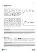
  • Page 33: Adjustment function During the ON/OFF adjustment, the thermostat switches on when the measured room temperature is below/above the desired temperature value and switches off when the desired temperature is reached. TPI If the thermostat is powered by a 230V power supply, it is possible to take advantage of the special TPI algorithm which optimises the system runtimes for a more constant comfort level, ensuring optimal energy savings. Default value = 1 1 = ON/OFF adjustment 2 = TPI adjustment Optimisation When the thermostat is set to the ON/OFF adjustment, this function allows minimising the energy consumption of the heating/cooling system by adjusting its on/off times according to the installed type of system and the set differential.
  • Page 34: Static differential allows setting the temperature difference between the OFF and ON modes. Default value is set to Standard, ranging from 0.3°C to 5°C. Pump Anti-seizure function prevents limestone deposits during system shutdowns. This function can be enabled by configuring the activation minutes of the circulating pump. Default value for Pump Anti-seizure is OFF, with a range of 1 to 10 minutes for activation. Virtual relay function displays the activity status of the system when the display is off. The central LED indicates system status with different colors for winter and summer. Default value for the virtual relay is OFF. Regulation for the virtual relay is available only for systems powered by a 230V power supply.
  • Page 35: Energy class is necessary for enabling the optimization of the system's runtimes. Default parameter is A4, with options ranging from A4 to G. The emission terminal identifies the final element of the heating/cooling system. By setting the emission terminal, the values of the Proportional Band and Adjustment Period are automatically set. Proportional band for radiators is 0.5°C, and for fan coils, it is 1°C. The TPI Adjustment Period indicates the duration of a system on+off cycle. Adjustment Period values are set automatically by setting the emission terminal. Default value for the Adjustment Period is 15 minutes. Functionality is only available for TPI adjustment. The emission terminal options include radiators, fan coils, and floor.
  • Page 36: Proportional band is the temperature range around the set point where TPI adjustment is active. Beyond the proportional band range, adjustment is of the ON/OFF type. The values of the proportional band are set automatically by setting the emission terminal. Default value for the proportional band is 0.5°C. The range for the proportional band is 0.5°C to 2.0°C. Functionality is only available for TPI adjustment. Enabling the thermostat reset restores settings to default values. Default value for reset is NO, meaning reset is disabled. YES means reset is enabled.
  • Page 37: Disposal The symbol of the crossed-out wheeled bin indicates that the product must be collected and disposed of separately from household waste. Batteries and the integrated accumulators may be disposed of together with the product. A black bar indicates that the product was placed on the market after August 13th, 2005. Participating in the separate collection of products and batteries contributes to the correct disposal of these materials. For more detailed information on the collection and recycling programs available in your country, contact the local authorities or the sales point where you purchased the product. General warranty conditions The conventional warranty lasts 24 months, starting from the date the equipment is installed. The warranty covers all parts of the equipment, except those subject to normal wear and tear resulting from use.
  • Page 38: Page 38
  • Page 39: Page 39