Home > BECA > Beca BHP-8000 C Room Thermostat User Guide

Beca BHP-8000 C Room Thermostat User Guide

(WIFI TYPE)  
BHP-8000 C  
Room Thermostat  
User Guide  
GeneralDetails
NameBeca BHP-8000 C Room Thermostat User Guide
MakeBECA
LanguageEnglish
FiletypePDF (Download)
File size5.61 MB
Download PDF
1 Star2 Stars3 Stars4 Stars5 Stars (1 votes, average: 5.00 out of 5)
Loading...
Beca BHT-9000 Thermostat User Guide
beca BAC-005 Series Thermostat User Guide
Beca BHT-6000 Series Round Thermostat User Guide
Beca BAC-1000 Series WiFi Thermostat User Guide
Beca BHT-002 Electric Heating Wifi Thermostat User Guide
Beca BHT-008 Heating Thermostat User Guide
Beca BHT-7000 Smart Knob Thermostat User Manual
Beca BAC-006 Zigbee Thermostat User Guide
Beca BHT-006 Series Thermostat User Manual
beca BAC-003 Series WiFi Thermostat Fan Coil User Guide

Beca BHP-8000 C Room Thermostat User Guide
Get the free PDF manual for the Beca BHP-8000 C Room Thermostat User Guide and access setup steps, usage instructions, and troubleshooting tips. 👉 View online or download now to keep your thermostat running smoothly!

Beca BHP-8000 C Room Thermostat User Guide Overview
Summary of Contents

  • Page 1: Room thermostat user guide.
  • Page 2: Technical data includes power supply specifications and current load details. The sensor operates within a temperature range of 42-122 ℉ (5~50℃) with an accuracy of ±1 F. The display temperature range is from 41~210 ℉ (5~99℃) and the ambient temperature range is 23~113℉ (-5~45℃). Ambient humidity is specified as 5~95% RH (non-condensing) and storage temperature is noted. Power consumption is less than 1.5W, and the shell material is PC+ABS (fireproof). Installation instructions include removing the old thermostat and wiring diagrams for different scenarios. There are specific hole distances for installation based on region, such as 62±5mm for Europe, China, and Japan, and 86±3mm for the USA and Italy. The protection class is IP20, and the document includes operating instructions and wire terminals. Capacitive touch buttons are mentioned, along with APP connection details. The guide provides an overview of its contents and includes information on dimensions and timing error.
  • Page 3: Welcome Thank you for your purchase. Your new thermostat will provide uniform and comfortable temperature control throughout every room in your property. Please read this installation/programming manual for comprehensive instructions on installing and operating your thermostat. Please ensure a suitably qualified person installs your thermostat and complies with all local regulations. In the box: Thermostat, marking tape, screws, power module, QC passed, user guide. Caution: Electrical shock or equipment damage hazard. Disconnect power supply before installation. Check whether the power supply is 24V; if it is 95-220V, thermostat can’t be used. Your thermostat carries a 24 months warranty from date of purchase. Service outside the warranty period may incur a charge.
  • Page 4: APP operation interface description (Heat pump thermostat) Indoor target temperature System mode: Display the current system mode. Tap it to switch the mode. Fan mode: Display the current fan mode. Tap it to switch the mode. Hold mode: Displays the current hold mode. Tap it to switch the mode. Target temperature: Turn up/down the target temperature. Setting: You can edit the setting of the device, such as schedule, holiday mode, fan run time, etc.
  • Page 5: Main page Indoor temperature WiFi Current state Target temperature System mode Fan mode Initial setting Emergency heating Automatic control of heating and cooling based on ambient temperature
  • Page 6: Fan runs at intervals to circulate indoor air. Fan runs continuously and automatically adjusts the running time according to the system. Manual mode and AP mode are available for operation. Temporary manual programming mode is indicated by a blinking icon. The touch button controls the system fan, menu, and clock settings. Users can set heat and cool temperatures as well as view outdoor temperature. Weather conditions such as sunny, cloudy, rain, and snow are displayed. Figures 2.9 to 2.12 illustrate various functions and settings.
  • Page 7: Installation Power off, remove the old thermostat. Do not remove the wall plate. Take a picture of your old thermostat wires how to connect to the terminal. Label the wires with tags. Network distribution mode: EZ Mode. Press and hold the button until the thermostat screen flashes. Operate according to the following figures.
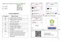
  • Page 8: Please confirm old thermostat if have C wiring (Blue line). Yes → Plan A No → Plan B Method 2: Scan the QR code to configure the network guide. What it means: - Terminals - Rh - Rc - C - 24VAC primary for heating - 24VAC primary for cooling - 24VAC Common Wire - Heat Relay (Stage 1) - Heat Relay (Stage 2) - Compress Relay (Stage 1) - Compress Relay (Stage 2) - Fan Relay - Optional wiring module terminal to combine Y and G, while reserving an extra in-wall wire to power on the thermostat. This QR code must be scanned in the app for quick jump thermostat pairing.
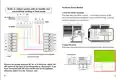
  • Page 9: About Wi-Fi connection Before using your Wi-Fi thermostat for the first time, you must configure the Wi-Fi signal and settings through your smartphone or tablet. This will allow communication between your connected devices. Remove the wall plate by unscrewing it from the wall and gently pulling it to ensure the wires do not fall back into the hole. Download your app by searching for Smartlife in the Apple Store or Google Play or using a browser to scan the QR code. Complete account registration and installation according to the guidance of the app. Connect the thermostat by checking the tutorial to complete the connection and setup. Connect the mobile phone to Wi-Fi and turn on Bluetooth. Wire the cables through the holes in the temperature controller mounting plate.
  • Page 10: Whether to turn on the outdoor compressor at the lowest temperature. Connect the wires to the base. Compressor outdoor minimum outdoor temperature: 0-20℃, default 2℃. Turn on the maximum temperature of the auxiliary heat. Auxiliary heat on outdoor maximum temperature: 0-18℃, default 18℃. Whether the heat pump compressor and auxiliary heat are turned on at the same time. If you have connected both the RC-wire and the RH-wire to the wall plate, adjust the DIP on the back of the thermostat. Interval temperature: 1.5-5℃, default 1.5℃. Cool & Heat set. Filter replacement countdown reminder: 0 to 180 days, default 180 days.
  • Page 11: Attach the thermostat on base. Schedule includes wake, heat, cool, and away settings. Advance options allow for temperature calibration and standby brightness adjustments. Power on your system to display the setup wizard for configuration. Temperature calibration ranges from -9 to 9 with a default of -4. Minimum and maximum temperature settings are adjustable. Compressor delay times can be set for one or two stages. Fan off delay time is adjustable. Cycle time for fan cycle mode ranges from 1 to 11 minutes.
  • Page 12: Operation What is power module? Power module requires your system to have specific wires. Selection of system mode includes options for cooling, heating, automatic control, emergency heating, and off. Selection of fan mode includes options for continuous running, automatic adjustment, and interval circulation. Selection of menu includes permanent hold, temporary hold, and using schedule. Setting the time involves adjusting minutes, hours, and weeks. The C-wire provides power to the thermostat. Child lock can be set by pressing and holding for 3 seconds. Programming mode allows setting schedules for different time periods. You can set temperatures for wake, away, home, and sleep periods.
  • Page 13: Install the power module. Find the HVAC terminals. Take a picture of the wires connected to the terminals of your old thermostat. Label the wires from the control board to the old thermostat. For dual heat and cooling system, if applicable. If you don’t have a c-wire, you will need the label below. Remove the jumper between Rh, Rc, or R terminals. Adjust the DIP switch on the back of the thermostat to 'Disconnect' if you have connected both RC-wire and RH-wire.
  • Page 14: Disconnect the wires of W/W1, Y/Y1, R to thermostat from control board. Reconnect these wires to the 4-terminal side of the power module. The wires and corresponding terminals are shown below. For dual heat and cooling system, if applicable, remove the jumper between Rh, Rc, or R terminals. Adjust the DIP switch on the back of the thermostat to 'Disconnect' if you have connected both RC-wire and RH-wire to the wallplate. Otherwise, switch it to the 'Connect' side.
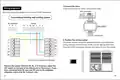
  • Page 15: Connect the wires to the HVAC control board side. Below are the wiring diagrams for common HVAC equipment. Conventional heating and cooling system includes components like W, C, G, Y, and R. The power module should be installed between your thermostat wiring and your control board. Install the power module at the right position and close the HVAC cover panel securely. For dual heat and cooling systems, remove the jumper between Rh, Rc, or R terminals. Adjust the DIP switch on the back of the thermostat to 'Disconnect' if both RC-wire and RH-wire are connected. Switch the DIP switch to 'Connect' if applicable.
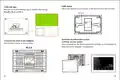
  • Page 16: DIP switch adjustment is necessary for connection. Add new tags to simplify wiring. Label the wires at your thermostat. If you don’t have a c-wire, use the provided labels. Connect the wires to the wallplate as indicated. Once powered up, the thermostat screen will display the setup wizard. Attach the thermostat to the base. Power on your system to complete configuration. Ensure correct wire connections for RC, C, S, W1, W2, O/B, RH, G, Y1, and Y2. Follow the wiring diagram for proper installation.