Home > Robertshaw > Robertshaw RS9220 Programmable Thermostat Installation Guide
Robertshaw RS9220 Programmable Thermostat Installation Guide


RS9220
Installation Manual

| General | Details |
|---|---|
| Name | Robertshaw RS9220 Programmable Thermostat Installation Guide |
| Make | Robertshaw |
| Language | English |
| Filetype | PDF (Download) |
| File size | 0.43 MB |


Robertshaw RS10420T WIFI Programmable Thermostat User Guide

Robertshaw RS8110 Non Programmable Thermostat Instruction Manual
Robertshaw RS8210 Thermostat Installation Guide

Robertshaw RS8210 Non-Programmable Multi-Stage 2H-1C Wall Thermostat User Manual

Robertshaw RS9220 Digital Programmable Wall Thermostat Instruction Manual

Robertshaw 9602 Programmable Thermostat User Manual

Robertshaw RS9320T Programmable Touchscreen Wall Thermostat Instruction Manual

Robertshaw RS9423T Thermostat Installation Guide

Robertshaw RTC500 WIFI Thermostat Instruction Manual

Robertshaw RS1110 Programmable 1 Heat 1 Cool Wall Thermostat Instruction Manual

Robertshaw RS9220 Programmable Thermostat Installation Guide Overview
Summary of Contents
- Page 1: Page 1
- Page 2: Thank you for purchasing a Robertshaw thermostat. This manual will describe how to install and test the Robertshaw RS9220 thermostat. Important safety information includes turning off power at the main power source before installing, removing, cleaning, or servicing the thermostat. Read all of the information in this manual before installing or programming this thermostat. This is a 24V AC low voltage thermostat. Do not install on voltages higher than 30V AC. All wiring must conform to local and national building and electrical codes and ordinances. Do not short (jumper) across terminals on the gas valve or at the system control to test installation. This will damage the thermostat and void the warranty.
- Page 3: Install the thermostat 4 to 5 feet above the floor in an area with good air circulation and average temperature. For new installations, mount the thermostat on an inside wall, 4-5 feet above the floor. Do not install the thermostat behind a door. Do not install the thermostat in a corner. Do not install the thermostat near air vents. Do not install the thermostat in direct sunlight. Do not install the thermostat with an outside wall behind it. Do not install the thermostat near any heat or steam generating fixtures. Do not install the thermostat near any concealed pipes or chimneys. Installation at these locations will affect thermostat operation.
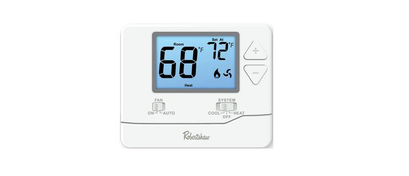
- Page 4: Getting to know your thermostat Displays the user selected set-point temperature. Room Hold: Is displayed when thermostat program is overridden. Low Battery Indicator: Replace batteries when indicator is shown. System Operation Indicators: The icon will display when the COOL, HEAT, or fan is on. Programmable Time Periods: This thermostat has 4 programmable time periods per day. Indicates the current room temperature. If these icons are flashing, there is a 5-minute delay for compressor protection. Temperature Set-Point Buttons. Easy Change Battery Door.
- Page 5: Wallplate installation This product is mercury-free. However, if this product is replacing a control which contains mercury, it needs to be disposed of properly. Contact your local waste management authority for instructions regarding recycling and proper disposal of the control. Disconnect power before installing this product. Failure to do so can cause electric shock or equipment damage. For a vertical mount, put screws on the top and bottom. For a horizontal mount, put screws on the left and the right.
- Page 6: Turn off power to heating/cooling system. Remove old thermostat but leave wallplate with wires attached. Do not remove wallplate.
- Page 7: Label the wires using the supplied wire labels as you disconnect them. Remove wallplate from the new thermostat and mount onto wall. Apply these wiring labels to each wire with the appropriate terminal designation as you remove it from the existing thermostat.
- Page 8: Mount the new wallplate using the included screws and anchors. Drill 3/16-in. holes for drywall. Drill 3/16-in. holes for plaster.
- Page 9: Connect wires by matching wire labels. If labels do not match letters on the thermostat, refer to Alternate Wiring (Conventional Systems) on page 9. Remove the metal jumper if both RH and Rc wires are present. Insert wires and tighten screws.
- Page 10: Wiring Alternate wiring (conventional systems) If labels do not match letters on the thermostat, check the chart below and connect to terminal as shown. If wires will be connected to both RC and RH/R terminals, remove metal jumper. If there is a C or X wire available then you can connect with C terminal. If there is no C or X wire then no need to connect with C terminal. If you have a heat pump without auxiliary/backup heat connect either the O or B, not both. If you do not have a heat pump, do not connect O or B. Wrap bare end of wire with electrical tape. Place a jumper (piece of wire) between Y and W if you are using a heat pump without auxiliary/backup heat.
- Page 11: Wiring Terminal designations include various components such as 24 VAC common, heat pump reversing valve, heat relay stages, and power for heating and cooling. Wire specifications recommend using 18- to 22-gauge thermostat wire. Shielded wire is not required. The common wire is optional when the thermostat is powered by batteries.
- Page 12: Wiring Power supply Optional 24 VAC common connection when thermostat is used in battery power mode Typical 2H/2C system: 1 transformer Typical 2H/2C system: 2 transformers Remove jumper Compressor relay Heat relay Fan relay
- Page 13: Wiring Typical heat-only system Typical cool only system Compressor relay Heat relay Fan relay Typical 2H/2C heat pump system without auxiliary Typical heat-only system with fan Cool reversing valve Heat reversing valve
- Page 14: Installer setup menu allows for easy configuration of the thermostat. Follow the procedure to set up the thermostat to match the specific heating/cooling system. Press MENU to access the setup. Press and hold TECH SET for 3 seconds. Configure the installer options using the provided table. Use arrows to change settings. Use NEW STEP or PREV STEP to navigate options. Only press DONE when you want to exit the installer setup options.
- Page 15: Installer setup menu includes settings for display and adjustment options. The filter change reminder can be adjusted from OFF to 2000 hours in 50-hour increments. Press the second button from the top left side of the thermostat to display the current filter elapsed run time. This setting will flash FILT in the display after the elapsed run time to remind the user to change the filter. The OFF setting will disable the filter change reminder feature. The room temperature display can be adjusted to read up to 3° above or below the factory calibrated temperature. The minimum compressor run time can be adjusted from OFF to 3, 4, or 5 minutes. If 3, 4, or 5 minutes is selected, the compressor will run for at least the selected time before turning off. The installer can select the minimum run time for the compressor to help protect it from short-cycling.
- Page 16: Installer setup menu includes settings for display and adjustment options. The compressor short cycle delay setting protects the compressor by preventing it from turning on for 5 minutes after it was last turned off. This setting can be removed by selecting OFF. The cooling differential is factory preset at 0.5°, activating the cooling system when the room temperature increases by this amount. If the cooling system activates too frequently, the temperature differential should be increased. The cooling differential setting is adjustable from 0.2°F to 2°F. The heating differential is factory preset at 0.4°, activating the heating system when the room temperature decreases by this amount. If the heating system activates too frequently, the temperature differential should be increased. The heating differential setting is adjustable from 0.2°F to 2°F.
- Page 17: Installer setup menu includes settings for display and adjustment options. Users can select between Fahrenheit or Celsius for temperature display. The clock can be set to either a 12 or 24 hour format. The operation mode can be selected as GAS or ELEC depending on the type of furnace.
- Page 18: Installer setup menu Settings Display Adjustment options This thermostat can be configured to have 7 Day, 5+1+1 programming or be non-programmable. If 7 Day is selected, in Set Time all seven days will need to be programmed individually. If 5+1+1 programming is selected, in Set Time Monday–Friday will be programmed together and Saturday and Sunday will need to be programmed individually. If 0d is selected, the thermostat becomes non-programmable.
- Page 19: Mounting thermostat involves aligning the 4 tabs on the faceplate with the corresponding slots on the back and pushing gently until it snaps into place. Battery installation is optional if used with AC power. During power outages, the batteries will save settings and power the display. Insert 2 AAA alkaline batteries.
- Page 20: Set time of day and day of week. Press MENU. Press SET TIME. Day of the week will be flashing. Use to select the current day of the week. Press NEXT STEP. The current hour will be flashing. Use to select the current hour. Note the correct a.m. or p.m. indicator is selected. Press DONE when completed.
- Page 21: Default program for energy saving operation is pre-programmed. Set-point temperatures for heat and cool are specified for different times. The schedule includes events for weekdays and weekends. Temperature settings vary between 62°F (17°C) and 83°F (28°C). Wake, leave, return, and sleep events are defined throughout the day. The program is designed to optimize comfort and energy efficiency. Specific times are set for each event during the week. The default program includes both heating and cooling set-points. Temperature adjustments are made based on the time of day. The thermostat aims to maintain a comfortable environment while saving energy.
- Page 22: You can use the table below to plan your customized program schedule. Custom program includes set-point temperatures for heat and cool, along with time events for each day of the week. The schedule allows for planning around weekdays and weekends. The table includes sections for wake, leave, return, and sleep times. Set-point temperatures can be adjusted for different times of the day. The program is designed to help customize heating and cooling based on individual schedules. This feature allows for energy efficiency and comfort. Users can fill in their specific times and temperatures. The programming is applicable for both Saturday and Sunday. The layout is structured to facilitate easy planning.
- Page 23: Custom programming allows for 7 Day or 5+1+1 scheduling. In 7 Day mode, each day must be programmed individually. In 5+1+1 mode, Monday to Friday is programmed together, while Saturday and Sunday are programmed individually. There are four time periods for each day: wake, leave, return, and sleep. Select heat or cool, as they need to be programmed separately. Follow the steps to customize your program schedule. Press menu to access scheduling options. Time and set-point temperature will be flashing during programming. Repeat steps for each time period for the selected days. Ensure to program all required time periods for both 5+1+1 and 7-day schedules.
- Page 24: Specifications Temperature display range: 41°F to 95°F (5°C to 35°C) Temperature control range: 44°F to 90°F (7°C to 32°C) Load rating: 1 amp per terminal, 1.5 amp maximum all terminals combined Display accuracy: 1°F Differential: Heating is adjustable from 0.2°F to 2.0°F; cooling is adjustable from 0.2°F to 2.0°F Power source: 18 to 30 VAC, NEC Class II, 50/60 Hz for hardwire; battery power from 2 AAA Alkaline batteries Operating ambient temperature: 32°F to +105°F (0°C to +41°C) Operating humidity: 90% non-condensing maximum Dimensions: 4.72”W x 3.86”H x 0.98”D
- Page 25: Page 25

GENERAL SENNA 300 Smart Room Thermostat User Manual

SALUS SQ610 Smart Thermostat User Guide

OUELLET OTL221 Single Pole Mechanical Thermostat Instructions

PURGEAR STC-2302 Digital Thermostat User Guide

GENERAL LIFE 230S RF Digital Room Thermostat User Manual

Honeywell TH2320WF4010 FocusPRO Smart Thermostat User Guide

Honeywell Home T10 Programmable Smart Thermostat Installation Guide

ENGO CONTROLS EFAN-230W Fan Coil Thermostat User Guide

Milesight WT30x Smart Fan Coil Thermostat User Guide

BEOK Color TFT-LCD Heating Thermostat User Manual