
Home > CLIMATE MASTER > CLIMATE MASTER CXM2 Communicating Awc Thermostat Installation Guide
CLIMATE MASTER CXM2 Communicating Awc Thermostat Installation Guide


iGATE 2 COMMUNICATING (AWC) THERMOSTAT – IOM
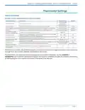
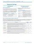
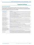
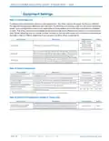
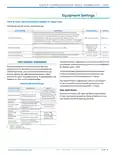
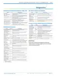
Equipment Settings
Table 10: Airflow Configuration
Range for the airflow settings will depend on model and capacity selection (in 25 cfm increments).
Tranquility systems must be paired with CV ECM fan motors for this functionality to be applicable. Please
reference the unit model number located on the unit data plate with the model nomenclature decoder in
the unit IOM to determine if your product contains a CV ECM.
Configuration Setting
Description
Configures the unit airflow while operating at minimum capacity in the heating mode. The installer
may wish to select a higher cfm than the nominal cfm for this setting to ensure proper air movement
during low-capacity operation.
Min Heating Airflow
(applies to Trilogy units)
Configures the unit airflow while operating at maximum capacity in the heating mode. The installer
may wish to select a lower cfm than the nominal cfm for this setting to avoid air velocity noise from
the ductwork during maximum capacity operation.
Max Heating Airflow
(applies to Trilogy units)
Configures the unit airflow while operating at minimum capacity in the cooling mode. The installer
may wish to select a higher cfm than the nominal 400 cfm/ton for this setting to ensure proper air
movement during low-capacity operation.
Min Cooling Airflow
(applies to Trilogy units)
Configures the unit airflow while operating at maximum capacity in the cooling mode. The installer
may wish to select a lower cfm than the nominal 400 cfm/ton for this setting to avoid air velocity noise
from the ductwork during maximum capacity operation.
Max Cooling Airflow
(applies to Trilogy units)
Low Dehumidification Airflow
(applies to Trilogy units)
High Dehumidification Airflow
(applies to Trilogy units)
Configures the unit airflow while operating at minimum capacity in the dehumidification mode.
Configures the unit airflow while operating at maximum capacity in the dehumidification mode.
Configures the unit airflow while operating at minimum capacity in the heating mode. The installer
may wish to select a higher cfm than the nominal cfm for this setting to ensure proper air movement
during low-capacity operation.
Heat Stage 1 Airflow
(applies to Tranquility units)
Configures the unit airflow while operating at maximum capacity in the heating mode. The installer
may wish to select a lower cfm than the nominal cfm for this setting to avoid air velocity noise from
the ductwork during maximum capacity operation.
Heating Stage 2 Airflow
(applies to Tranquility units)
Auxiliary Heat Airflow
(applies to Tranquility units)
Configures the unit airflow during the auxiliary heat mode (if applicable).
Emergency Heat Airflow
Configures the unit airflow during the emergency heat mode (if applicable).
Configures the unit airflow while operating at minimum capacity in the cooling mode. The installer
may wish to select a higher cfm than the nominal 400 cfm/ton for this setting to ensure proper air
movement during low-capacity operation.
Cool Stage 1 Airflow
(applies to Tranquility units)
Configures the unit airflow while operating at maximum capacity in the cooling mode. The installer
may wish to select a lower cfm than the nominal 400 cfm/ton for this setting to avoid air velocity noise
from the ductwork during maximum capacity operation.
Cooling Stage 2 Airflow
(applies to Tranquility units)
Cool Dehumidification Stage 1
Airflow (applies to Tranquility units)
Cool Dehumidification Stage 2
Airflow (applies to Tranquility units)
Configures the unit airflow while operating at minimum capacity in the dehumidification mode.
Configures the unit airflow while operating at maximum capacity in the dehumidification mode.
Configures the unit airflow while operating in the continuous fan mode.
Constant Fan Airflow
This setting determines whether (and how long) the blower will continue to operate after the compressor
has cycled off at the end of each heating cycle (0 seconds to 255 seconds, in 5 second increments).
This setting determines whether (and how long) the blower will continue to operate after the compressor
has cycled off at the end of each cooling cycle (0 seconds to 255 seconds, in 5 second increments).
Heat Off Delay
Cool Off Delay
Part#: 97B0132N01 | Revised: Februar y 06, 2025
PAG E : 1 3
w w w. c l i m a te m a s te r. c o m

| General | Details |
|---|---|
| Name | CLIMATE MASTER CXM2 Communicating Awc Thermostat Installation Guide |
| Make | CLIMATE MASTER |
| Language | English |
| Filetype | PDF (Download) |
| File size | 1.03 MB |
 (1 votes, average: 5.00 out of 5)
 Loading...


hawco AC2-5 Two Stage Thermostat Instruction Manual

STELPRO STZW402 – KI Electronic Thermostat Owner’s Manual

KONIGHAUS Remote Infrared Heater Plus Thermostat User Guide

SALUS HTRS-RF Wireless Digital Thermostat Instruction Manual

REHAU 13280001001 Thermostat Installation Guide

Decdeal HY607 WIFI Digital Heating Thermostat User Manual

Honeywell TH2110U4004 Thermostat User Guide

heatmiser neoStat-e Electric Floor Heating Thermostat Instructions

Honeywell TH5000 Series FocusPRO Non-Programmable Digital Thermostat Installation Guide

SALUS RT310TX Wireless Programmable Thermostat User Guide