Danfoss ECtemp 132 Electronic Thermostat Installation Guide


Installation Guide
ECtemp 132
Electronic Thermostat
electricheating.danfoss.com

| General | Details |
|---|---|
| Name | Danfoss ECtemp 132 Electronic Thermostat Installation Guide |
| Make | Danfoss |
| Language | English |
| Filetype | PDF (Download) |
| File size | 0.32 MB |


Danfoss RET-MD Electronic Intelligent Dial Setting Thermostat Installation Guide
Danfoss VICUQ24M Icon Programmable II Room Thermostat Installation Guide

Danfoss MBC 8000, MBC 8100 Heavy Duty Thermostat Installation Guide

Danfoss UT 72-UT 73 Universal Thermostat Installation Guide

Danfoss ECtemp 530 Electronic Thermostat Installation Guide

Danfoss 014G0251 Eco Radiator Thermostat User Guide

Danfoss 014G0013 Z Wave Radiator Thermostat Installation Guide

Danfoss RET230P Electronic Thermostat Instruction Manual

Danfoss TP7000 Range Electronic 7 Day Programmable Room Thermostat Installation Guide

Danfoss RET1000 Series Electronic Thermostat User Guide

Danfoss ECtemp 132 Electronic Thermostat Installation Guide Overview
Summary of Contents
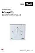
- Page 1: Installation guide for the ECtemp 132 electronic thermostat.
- Page 2: Installation guide
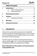
- Page 3: Introduction ECtemp 132 is an electronic thermostat to be installed directly on the wall. It is provided with a room sensor to control the room temperature and an additional floor sensor to limit the maximum floor temperature. The thermostat has a button for adjusting the temperature, with a scale from 5 - 45 °C, and an LED indicator showing standby (green light) and heating periods (red light). Technical specifications Safety instructions Mounting instructions Settings Temperature settings Warranty Disposal instruction
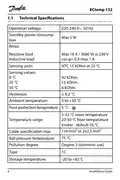
- Page 4: Technical specifications include operation voltage of 220-240 V~, 50 Hz and a maximum power of 5 W. The standby power consumption is specified. Relay specifications indicate a maximum of 16 A / 3680 W at 230 V. The sensing units use NTC 15 kOhm at 25 °C. Sensing values range from 0 °C to 50 °C with corresponding resistance values. Hysteresis is set at 0.2 °C. Ambient temperature ranges from 5-35 °C for room temperature and 20-50 °C for floor temperature. The cable specification allows for a maximum of 1x4 mm² or 2x2.5 mm². The storage temperature is between -20 to +65 °C.
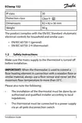
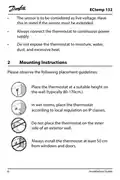
- Page 5: ECtemp 132 Protection class Dimensions Weight The product complies with the EN/IEC Standard «Automatic electrical controls for household and similar use»: EN/IEC 60730-1 (general) EN/IEC 60730-2-9 (thermostat) Make sure the mains supply to the thermostat is turned off before installation. When the thermostat is used to control a floor heating element in connection with a wooden floor or similar material, always use a floor sensor and never set the maximum floor temperature to more than 35°C. The installation of the thermostat must be done by an authorized and qualified installer according to local regulations.
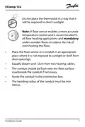
- Page 6: The sensor is to be considered as live voltage. Always connect the thermostat to continuous power supply. Do not expose the thermostat to moisture, water, dust, and excessive heat. Place the thermostat at a suitable height on the wall (typically 80-170cm). In wet rooms, place the thermostat according to local regulation on IP classes. Do not place the thermostat on the inner side of an exterior wall. Always install the thermostat at least 50 cm from windows and doors.
- Page 7: Do not place the thermostat in a way that it will be exposed to direct sunlight. A floor sensor enables a more accurate temperature control and is recommended in all floor heating applications and mandatory under wooden floors to reduce the risk of over-heating the floor. Place the floor sensor in a conduit in an appropriate place where it is not exposed to sunlight or draft from door openings. Equally distant and >2cm from two heating cables. The conduit should be flush with the floor surface - countersink the conduit if necessary. Route the conduit to the connection box. The bending radius of the conduit must be min 50mm.
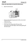
- Page 8: Follow the steps below to mount the thermostat. Open the thermostat. Remove the button to get access to the screw that holds the front. Loosen the screw. Push down the release tab at the top of the thermostat using a flat object while slowly pulling off the front cover.
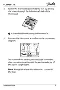
- Page 9: Fasten the thermostat directly to the wall by driving the screws through the holes in each side of the thermostat. Connect the thermostat according to the connection diagram. The screen of the heating cable must be connected via a connector together with the earth conductor of the power supply cable. Always install the floor sensor in a conduit in the floor. Max load is 16 (1) A at 220-240V~. The device has an IP30 rating. Screw holes are provided for fastening the thermostat. Installation guide is included. Ensure proper connection of load and neutral wires. Follow safety precautions during installation.
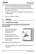
- Page 10: Set the maximum floor temperature between 20° and 50 °C using a thin screwdriver on the black electronic component with temperature indications. Install the front cover and button in the reverse order of disassembly. Turn on the power supply. How to change the minimum and maximum floor temperatures involves lifting off the adjustment button with a thin screwdriver. Move the pins to the desired positions and put the adjustment button back in place. The floor temperature is measured where the sensor is placed.
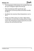
- Page 11: The temperature of the bottom of a wooden floor can be up to 10 degrees higher than the top. Floor manufacturers often specify the max temperature on the top surface of the floor (usually 27-28 °C). By default, the maximum floor temperature is set to 35 °C. Always use a floor sensor or a room + floor sensor combination to control floor heating. Without a floor sensor, the temperature control may be less accurate and you risk overheating the floor. Installation guide.
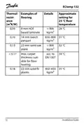
- Page 12: Thermal examples of floor resistance flooring. Approximate setting for 25 °C temperature. Max. carpet thickness suitable for floor heating acc. to EN 1307. Installation guide.
- Page 13: Installation guide
- Page 14: Warranty A 2-year product warranty is valid for thermostats: ECtemp 132. Danfoss offers warranty valid from the date of purchase under specific conditions. During the warranty period, Danfoss will offer a new comparable product or repair the product if found faulty due to defective design, materials, or workmanship. The decision to repair or replace is at the discretion of Danfoss. Danfoss is not liable for consequential or incidental damages. The warranty is valid only if the WARRANTY CERTIFICATE is completed correctly and proof of purchase is provided. The WARRANTY CERTIFICATE must be filled in, stamped, and signed by the authorized installer. Danfoss warranty does not cover damage from incorrect use or installation by unauthorized electricians. All work will be invoiced if Danfoss inspects or repairs faults due to incorrect conditions. The warranty explicitly excludes all claims exceeding the stated conditions.
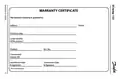
- Page 15: Warranty certificate The Danfoss warranty is granted to: Purchase date Serial number of the product Product Art. No. Connected output [W] Installation date & signature Connection date & signature
- Page 16: Disposal instruction Installation guide
- Page 17: Installation guide
- Page 18: Installation guide
- Page 19: Danfoss ECtemp 132 Produced by Danfoss © 04/2024
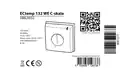
- Page 20: Product documentation Designed in Denmark for Danfoss A/S Temperature limit +20 to +50°C Operating voltage 220-240V~ Frequency 50-60Hz~ Current rating 16A/3680W@230V~ IP rating IP 30 Operating temperature range +5 to +35°C

Danfoss RAS-D2 Radiator Thermostat Installation Guide

GENERAL LIFE NORA 270S Smart Digital Room Thermostat Instruction Manual

ENGO CONTROLS EFAN-230W WIFI 230V Fan Coil Thermostat User Guide

GENERAL LIFE HT250S Digital Room Thermostat User Manual

HIVE HAH2INSTAMZ-01 Active Heating Thermostat User Guide

EPH CONTROLS COMBIPACK3 Wireless Non Programmable Thermostat User Guide

Vaillant VRC 700 Programmable Weather Compensating Thermostat Owner’s Manual

Generic HY610 WiFi Digital Heating Thermostat User Manual

PNi CT36PRO Smart Thermostat Instruction Manual

Danfoss Eco Electronic Radiator Thermostat Instruction Manual