Home > WHITE RODGERS > White Rodgers 1F85-0422 Blue Universal Thermostat Instruction Manual
White Rodgers 1F85-0422 Blue Universal Thermostat Instruction Manual
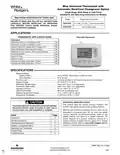


Blue Universal Thermostat with
Automatic Heat/Cool Changeover Option
Single Stage, Multi-Stage or Heat Pump
Installation and Operating Instructions for Models:
Save these instructions for future use!
Model
Programming Choices
FAILURE TO READ AND FOLLOW ALL INSTRUCTIONS
CAREFULLY BEFORE INSTALLING OR OPERATING
THIS CONTROL COULD CAUSE PERSONAL INJURY
AND/OR PROPERTY DAMAGE.
5/1/1 Day 5/2 Day Non-Programmable
Non-Programmable
1F85-0422
1F83-0422
APPLICATIONS
THERMOSTAT APPLICATION GUIDE
1F83-0422 Thermostat
Description
Heat Pump (No Aux. or Emergency Heat)
Heat Pump (with Aux. or Emergency Heat)
Systems with up to 2 Stages Heat, 2 Stages Cool
Heat Only Systems (with optional fan switch)
Millivolt Heat Only Systems – Floor or Wall Furnaces
Cool Only Systems
Yes
Yes
Yes
Yes
Yes
Yes
Yes
Yes
Yes
Yes
Gas or Oil Heat
Electric Furnace
Hydronic (Hot Water) Zone Heat – 2 Wires
Hydronic (Hot Water) Zone Heat – 3 Wires
SPECIFICATIONS
Electrical Rating:
Battery Power.................................................... mV to 30 VAC, NEC Class II, 50/60 Hz or DC
Input-Hardwire................................................... 20 to 30 VAC
Terminal Load........................................................... 1.5 A per terminal, 2.5A maximum all terminals combined
Setpoint Range......................................................... 45° to 90°F (7° to 32°C)
Differential (Single Stage)......................................... Heat 0.6°F; Cool 1.2°F (adjustable)
Differential (Heat Pump) ........................................... Heat 1.2°F; Cool 1.2°F (adjustable)
Operating Ambient.................................................... 32° to +105°F (0° to +41°C)
Operating Humidity................................................... 90% non-condensing max.
Shipping Temperature Range ................................... -4° to +150°F (-20° to +65°C)
Dimensions Thermostat............................................ 3-7/8”H x 5-1/8”W x 1-1/4”D
ATTENTION: MERCURY NOTICE
This product does not contain mercury. However, this
product may replace a product that contains mercury.
CAUTION
!
To prevent electrical shock and/or equipment damage,
disconnect electric power to system at main fuse or
circuit breaker box until installation is complete.
Mercury and products containing mercury must not be
discarded in household trash. Do not touch any spilled
mercury. Wearing non-absorbent gloves, clean up any
spilled mercury and place in a sealed container. For
proper disposal of a product containing mercury or a
sealed container of spilled mercury, place it in a suitable
location to send product containing mercury.
Index
Page
Installation
2
2
3
4
6
7
8
Wiring Connections
Thermostat Quick Reference
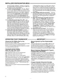
Installer Configuration Menu
Operating Your Thermostat
Programming
Troubleshooting
PART NO. 37-7136A
1007

| General | Details |
|---|---|
| Name | White Rodgers 1F85-0422 Blue Universal Thermostat Instruction Manual |
| Make | WHITE RODGERS |
| Language | English |
| Filetype | PDF (Download) |
| File size | 0.38 MB |


White-Rodgers 1E78 Non Programmable Heat Only Thermostat User Manual

White-Rodgers 1F97-1277 Big Blue Single Stage Thermostat User Manual

White-Rodgers 1F56N-444 Thermostat User Manual

White-Rodgers 1F83-277 Heating & Air Conditioning Auto Changeover Heat Pump Thermostat User Manual

White-Rodgers M30 Thermostat Instruction Manual

WHITE-RODGERS 1F51N-619 Low Voltage Evaporative Cooler Thermostat Instruction Manual

White Rodgers 1F78-151 Non Programmable Thermostat Instructions

WHITE RODGERS 1F80-51 Programmable Electronic Digital Thermostat Instruction Manual

WHITE-RODGERS 1F86-0471 Blue Single 1 1 Stage Thermostat Instruction Manual

WHITE-RODGERS 1F90-71 5-Day 2-Day Electronic Digital Thermostat Instruction Manual

White Rodgers 1F85-0422 Blue Universal Thermostat Instruction Manual Overview
Summary of Contents
- Page 1: Blue universal thermostat with automatic heat/cool changeover option. Single stage, multi-stage or heat pump installation and operating instructions for models. Save these instructions for future use. Failure to read and follow all instructions could cause personal injury and/or property damage. Thermostat application guide includes various system types. Specifications include electrical rating and setpoint range. Operating ambient temperature ranges from 32° to +105°F. This product does not contain mercury but may replace a product that does. To prevent electrical shock, disconnect electric power before installation. Refer to the index for installation, wiring connections, and troubleshooting.
- Page 2: INSTALLATION Thermostat installation and all components of the control system shall conform to Class II circuits per the NEC code. A standard heat/cool thermostat consists of three basic parts: the cover, the base, and the switching subbase. Before removing wires from the old thermostat, label each wire with the terminal designation from which it was attached. For best results, replace all batteries with new premium brand alkaline batteries such as Duracell or Energizer. If the home is going to be unoccupied for an extended period and is displayed, the batteries should be replaced before leaving. Leveling is for appearance only and will not affect thermostat operation. To install the batteries, pull the battery door as shown by the arrow and lift open. Refer to equipment manufacturers’ instructions for specific system wiring information. Terminal designation descriptions include indicators for heat pump malfunction, changeover valves, compressor relay, and fan relay. Refer to the configuration section for proper thermostat configuration.
- Page 3: Thermostat quick reference Home screen description Displays the power level of the 2 “AA” batteries. “Change” indicates batteries are low and should be replaced with 2 new premium brand “AA” Alkaline batteries. “System On” indicates when heating or cooling stage is energized. Displays “Save” when Cool Savings is working. Displays “Heat Pump” when system is configured as Heat Pump thermostat. The word “HOLD” is displayed when the thermostat is in the HOLD mode. Displays “Change Filter” when the system has run for the programmed filter time period. Displays “Set” for setpoint when in Run Program mode. “Call For Service” indicates a fault in the heating/cooling system. Displays Fan Mode (On, Auto) or “Run Sched” in Menu mode.
- Page 4: INSTALLER/CONFIGURATION MENU With thermostat in Heat, Cool or Auto, in normal operation, press the Menu button for at least 5 seconds. Selects Keypad Lockout. Selects Keypad lockout combination number. Selects Multi-Stage, Heat Pump, or Single Stage. GAS setting: furnace controls the blower. ELE setting: thermostat controls the blower. Selects Cool Savings Value 1 (low) to 6 (high). Selects Energy Management Recovery On or Off. Adjustable Anticipation: Selects heating cycle rate for MS or SS. Selects Display Light On or OFF.
- Page 5: Keypad lockout allows the keypad to be locked or unlocked. Energy management recovery enables early heating or cooling to reach setpoint temperatures. Cycle rate selection determines the frequency of heating and cooling cycles. Compressor lockout helps protect the compressor from short cycling. The thermostat can be configured for different system types, including multi-stage and heat pump systems. Fan operation can be set for gas or electric systems. Cool savings feature adjusts the setpoint temperature to reduce cooling costs during high demand. Backlight display improves visibility in low lighting conditions. Temperature display adjustment allows for calibration of the displayed temperature. Limited heat and cool range features set maximum and minimum temperature limits for heating and cooling.
- Page 6: Installer/configuration menu Comfort Alert with active protection allows the thermostat to identify fault codes sent by the Comfort Alert module and react by turning the compressor off. Select automatic schedule to program a desired comfort temperature into all program periods with a 6°F setback for night periods. Select daylight saving time calculation to allow the thermostat to calculate DST automatically. Select filter replacement reminder to set a reminder for changing or cleaning the air filter after a specified run time. Select fast second stage ON or OFF to control the second stage heating or cooling based on temperature adjustments. Select reversing valve output to accommodate heat pump applications requiring a changeover relay. Choose the fan setting (Auto or On) to control when the fan operates. Manual operation for non-programmable mode allows you to select heat or cool and adjust the temperature. Choose the system setting (Heat, Off, Cool, Auto, Emer) to control the heating and cooling systems. Program override allows temporary adjustments to the temperature setting for a specified duration.
- Page 7: Programming (for programmable model only) Set current time and date Press MENU and then TIME button once. The display will show the hour only. Press and hold either the or key to adjust the start time for the 1st period. The time will change in 15 minute increments. After you have set the time and the temperature for the period to begin, press SCHEDULE to advance to the next program period. Repeat steps until all of the program times and temperatures are set for all program periods on that day. When programming is complete and all of the times and temperatures match your desired heating schedule, press RUN SCHEDULE. Enter the heating program by pressing SYSTEM button to select “Heat.” Enter the cooling program by pressing SYSTEM button to select “Cool.”
- Page 8: Programming your program – important The heating and cooling program schedules allow you to pencil in your own program times and temperatures. The 1F85-0422 comes configured for 5/1/1 day programming and can also be configured for 5/2 day programming. Keep the following guidelines in mind when planning your program: In heating, lower temperatures will save energy. In cooling, higher temperatures will save energy. If you plan on using auto changeover, do not program the heating higher than the cooling. Worksheet for re-programming 5/2 day and 5+1+1 day program. Comfort alert codes The Comfort Alert diagnostics product monitors the air conditioning outdoor systems with single phase Copeland Scroll compressors. Abnormal system and electrical conditions are indicated by flashing alert codes on the yellow LED on the Comfort Alert module. The Comfort Alert compatible thermostat displays “Call For Service” that flashes at the same rate as the yellow LED on the Comfort Alert module.
- Page 9: Troubleshooting Reset operation When thermostat is reset, installer configuration menu settings and programming will reset to factory settings. If a voltage spike or static discharge blanks out the display or causes erratic thermostat operation, you can reset the thermostat by removing the wires from terminals R and C. Be sure to review the installer configuration menu settings. To reset the programming, clock and configuration settings, press and the FAN button simultaneously. Common problems include blown fuse, tripped circuit breaker, or loose connections. For no heat, check if the pilot light is lit or if the furnace is in a lock-out condition. Diagnostic: Set SYSTEM Switch to HEAT and raise the setpoint above room temperature. For no cool, check if the cooling system requires service or if the thermostat needs replacement. Thermostat thermometer setting requires adjustment; it can be adjusted +/- 4 degrees. If the furnace cycles too fast or too slow, the location of the thermostat may be influencing the cycle rate.
- Page 10: Page 10
- Page 11: Page 11
- Page 12: Page 12

BEOK CONTROLS TCR8 IPS Colorful LCD Screen Smart Thermostat Owner’s Manual

ESPUK ECSPST Fort Programmable Thermostat User Manual

AuVerte 003001.C508 Thermostat Installation Guide

GENERAL LIFE FH104S Underfloor Heating Thermostat User Manual

BEOK CONTROLS BOT-R6W Boiler Thermostat User Guide

Honeywell CM907 Programmable Room Thermostat User Guide

Robertshaw RS10420T WIFI Programmable Thermostat User Guide

Danfoss 015G3090 React Radiator Thermostat Installation Guide

Honeywell RLV450 Programmable Thermostat

Hydro Smart HSRADSTATWIFI HSRadStat Wi Fi Thermostat User Guide