Home > OLIMPIA SPLENDID > OLIMPIA SPLENDID 9899 Thermostat User Manual
OLIMPIA SPLENDID 9899 Thermostat User Manual


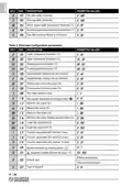


Pollution rating:
2
Tracking index (PTI):
Class of rating against electric shock:
Impulse withstand voltage:
Number of manual cycles:
Number of automatic cycles:
Software class:
175
II
2500V
50000
100000
A
E
M
C
t
e
s
t
v
o
l
t
a
g
e
:
230 V~ 50 Hz
34 mA
EMC test current:
‘Short’ fault mode exclusion distance tol- ±0.15 mm
erance:
Ball pressure test temperature:
Operating temperature:
Storage temperature:
Humidity limits:
Case:
75°C (167°F)
0°C .. 40°C (32°F .. 104°F)
-10°C .. +50°C (14°F .. 122°F)
20% .. 80% RH (non-condensing)
material:
ABS + PC V0 fire-retardant
Signal white (RAL 9003)
132 x 87 x 23.6 mm (L x H x D)
~ 265 g.
colour:
Dimensions:
Weight:
CLASSIFICATION ACCORDING TO REG. 2013.811.EC
Class:
V
Energy efficiency contribution: 3%
3%
IT - 12
| General | Details |
|---|---|
| Name | OLIMPIA SPLENDID 9899 Thermostat User Manual |
| Make | OLIMPIA SPLENDID |
| Language | English |
| Filetype | PDF (Download) |
| File size | 5.17 MB |


Honeywell Communicating Fan Coil Thermostat Instruction Manual

DAIKIN DKN509 Wireless Communicating Thermostat Instruction Manual

TCL IPOWER Heat Mat Thermostat Instruction Manual

HITACHI ATW-RTU-11 Wireless Thermostat Instruction Manual

JUMO B 60.3070.0 Surface Mounting Thermostat Room Thermostat Instruction Manual

SALUS CONTROLS SQ610 Quantum Smart Thermostat User Guide

Aprilaire S86WMUPR Programmable Wi-Fi Multi Stage Universal Thermostat Installation Guide

AuVerte C504 Ondur Elegant Temperature Control Thermostat Installation Guide

Honeywell Home DT4R Wireless Room Thermostat User Guide

SIEMENS RDE100.1 Programmable Room Thermostat Instruction Manual