Home > OLIMPIA SPLENDID > OLIMPIA SPLENDID 9899 Thermostat User Manual
OLIMPIA SPLENDID 9899 Thermostat User Manual


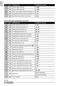


LEGEND
V COOL:
OUTPUT DRIVE SEQUENCES
Cooling valve proportional
output
Ts hea Ts Ts coo
10V
Heating valve proportional
output
V
COOL
5V
0V
V HEAT:
Ta
V FAN:
HEAT:
COOL:
Ta:
Fan proportional output
10V
ON-OFF Heating valve output
ON-OFF Cooling valve output
Room temperature
5V
0V
V
HEAT
Ta
Ta
10V
Ts:
Set-point temperature
V
FAN
5V
0V
Ts hea:
Ts coo:
ist:
Heating set-point temperature
Cooling set-point temperature
Ambienttemperaturehysteresis
Heating proportional band
Neutral zone amplitude
Bp hea
C03
Bp coo
C04
ZN
P20
Bp hea:
ZN:
The diagram illustrates the valve drive sequence in
a 4-pipe system with neutral zone. In the diagram
it is assumed that the outputs are configured for
proportionaldirectaction(0..10V),whileanyeffects
ofthesupplementarytimearedisregarded.Similarly,
in the case of a 2-pipe system, the valve output
(heating valve output) would be driven at the same
way. In this case Ts (set-point temperature) would
coincide with Ts ris in winter, and Ts raf in summer.
Bp coo:
Cooling proportional band
LEGEND
V COOL:
Cooling valve proportional
output
Ts hea Ts Ts coo
Heating valve proportional
output
ON
COOL
V HEAT:
Ta
OFF
V FAN:
HEAT:
COOL:
Ta:
Fan proportional output
ist
ist
P19
P19
ON-OFF Heating valve output
ON-OFF Cooling valve output
Room temperature
ON
HEAT
Ta
Ta
OFF
10V
Ts:
Set-point temperature
V
FAN
5V
0V
Ts hea:
Ts coo:
ist:
Heating set-point temperature
Cooling set-point temperature
Ambienttemperaturehysteresis
Heating proportional band
Neutral zone amplitude
Bp hea
C03
Bp coo
C04
ZN
P20
Bp hea:
ZN:
The diagram illustrates the valve drive sequence
in a 4-pipe system with neutral zone. Similarly, the
heating valve output (HEAT) in a 2-pipe system
would be driven in the same way. In this case, Ts
(set-point temperature) would coincide with Ts ris
in winter and Ts raf in summer.
Bp coo:
Cooling proportional band
This diagram disregards the effects of the supplementary time, if any, and assumes that the fan
proportional output (V FAN) is configured for direct action (P05=0) and a 0..10V signal (C15=0; C16
=100). The fan proportional output is always turned off (0V) when the COOL or HEAT valve output,
is off (not shown on the diagram).
IT - 5
| General | Details |
|---|---|
| Name | OLIMPIA SPLENDID 9899 Thermostat User Manual |
| Make | OLIMPIA SPLENDID |
| Language | English |
| Filetype | PDF (Download) |
| File size | 5.17 MB |


WATTS Tekmar Wi-Fi Thermostat Instruction Manual

LAE AC1-2W Digital Thermostat Instruction Manual

GENERAL Life SENNA 300 RF Wireless Room Thermostat User Guide

degrii THM-C Smart Thermostat Installation Guide

STELPRO STF362NP Floor Heating Thermostat Owner’s Manual

BAXI uSense 2 Wired Smart Thermostat Gateway Installation Guide

technolysis HYT002-WIFI WI-FI Digital Heating Thermostat User Manual

heatit Z-Temp2 Wireless Thermostat Instruction Manual

GLOBAL WIFI Digital Heating Thermostat User Manual

SALUS RT310 Thermostat User Manual