Home > OLIMPIA SPLENDID > OLIMPIA SPLENDID 9899 Thermostat User Manual
OLIMPIA SPLENDID 9899 Thermostat User Manual


THERMOSTAT
INSTALLATION AND USER MANUAL
EN

| General | Details |
|---|---|
| Name | OLIMPIA SPLENDID 9899 Thermostat User Manual |
| Make | OLIMPIA SPLENDID |
| Language | English |
| Filetype | PDF (Download) |
| File size | 5.17 MB |


OLIMPIA SPLENDID 9899 Thermostat User Manual Overview
Summary of Contents
- Page 1: Thermostat installation and user manual.
- Page 2: Installation instructions should follow the appropriate wiring diagram and possible variants. Electrical connections must be read carefully. 230V power supply is the factory setting. 24V power supply is also available. 50Hz frequency is the factory setting. 60Hz frequency is an alternative option. Parameter setting can be enabled or disabled. Configuration of parameters is crucial for proper operation. Refer to the figures for visual guidance on jumper configuration. Ensure all connections are secure and compliant with specifications.
- Page 3: Wiring diagram Select 230/24 V~ 0..10 V heating signal output 0..10 V cooling signal output 0..10V fan signal output Heating valve output Cooling valve output Remote input for activating the Centralised Heating/Cooling function Remote input for activating the Economy function Electronically commutated motor Remote input for activating the Window contact function
- Page 4: Wiring diagram for driving 2 on-off 230 V actuators in 4 pipe systems with proportional fan drive. Wiring diagram for driving 2 on-off 24 V actuators in 4 pipe systems with proportional fan drive. Wiring diagram for driving a 0..10V 24 V actuator for an integrated heating element system and a proportional fan drive. Wiring diagram for driving two 0..10V 24 V actuators in 4 pipe systems and a 230 V three speed motor.
- Page 5: 2-pipe system with ON-OFF valve. 2-pipe system with 0..10V servo drive. 4-pipe system with two ON-OFF valves. 4-pipe system with two 0..10V servo drives. Integrated electric heating element system with ON-OFF valve. Integrated electric heating element system with 0..10V servo drive. Connecting a fan to a three speed motor. Connecting a proportional fan to an EC motor with 0..10V input.
- Page 6: Cooling valve proportional output Heating valve proportional output Fan proportional output Set-point temperature Heating set-point temperature Cooling set-point temperature Ambient temperature hysteresis Heating proportional band Cooling proportional band The diagram illustrates the valve drive sequence in a 4-pipe system with neutral zone.
- Page 7: General information This integrated electronic regulation device is a digital thermostat for controlling the temperature in rooms that are heated or cooled by fan coil units. It provides continuous, proportional control over the valves and fan via 0..10V outputs. The device is also fitted with three ON/OFF relay outputs that can be used to control a fan with three speed settings or two ON/OFF actuators. The room temperature can be monitored by the internal or remote probe (optional). Description of controls The controller is equipped with five control buttons. Use the On/Off button to switch the controller on and off. Use the Speed button to modify the fan speed setting as desired. Each time the user presses the button, the fan speed is modified in a specific sequence. Use the Menu button to change the display readout mode.
- Page 8: Use these buttons to select the desired room temperature and configuration parameters. The controller is equipped with an LCD display, which indicates the temperature and settings. The symbols that may appear on the display are described in the following table. The controller switches automatically between heating/cooling modes. Heating active. Cooling active. Regulation suspended; the contact has detected an open window. The supply water temperature is too low (heating) or too high (cooling). Clogged filter (the filter must be cleaned). Display water temperature value. Temperature regulation in Economy mode.
- Page 9: The fan speed symbols indicate the fan status: when they are all extinguished, it indicates that the fan is off, whereas when they are illuminated it indicates that the fan is on. If the controller is configured to control the fan via the 0..10V proportional output, the higher the fan speed, the more fan dashes will be displayed in the fan symbol. The symbols indicate the status of the valve outputs, which varies depending on the type of system. For a two pipe system, the heating mode has the valve open, and the cooling mode also has the valve open. In a four pipe system, the heating valve is open in heating mode, and the cooling valve is open in cooling mode. The symbols associated with a proportional valve output are displayed even if the proportional valve is set to a minimum opening position. The symbols may also flash, indicating that the corresponding output should be on, but is temporarily disabled by another function. To install the device, release the plate attached to the controller base by pushing it to the left. Secure the plate to the wall using the two screw holes with pitch distances of 60 mm or 85 mm. If necessary, configure the jumpers JP1, JP2, JP3, JP4, and JP5.
- Page 10: Install the electrical connections in accordance with the appropriate wiring diagram and the possible variants. Read the “ELECTRICAL CONNECTIONS” paragraph carefully. Position the two teeth on the upper part of the cover so they enter the corresponding notches. The supply water sensor must be installed so it can monitor the water temperature correctly, even if the valve interrupts the flow. The same remote temperature sensor may not be connected to the terminals of more than one controller. The remote sensors, bimetallic contact, and window contact connected to the controller must be isolated from earth and the mains supply voltage. Failure to observe the above conditions may result in irreversible damage to the product. The appliance must be connected to the electric mains via a switch capable of disconnecting all poles in compliance with the current safety standards. This appliance must be installed and wired by qualified technicians and in compliance with the current standards. Make sure the mains power is off before wiring the appliance.
- Page 11: A window contact may be connected to terminals 14 and 16. Read the paragraph “ATTENTION” for the restrictions on the use of window contacts. The function associated with input terminals 3, 4 and 16 may be modified in parameters C17, C18 and C19. The RS connector, or alternatively terminals 14 and 15, may be used to connect an external environmental temperature sensor. Change configuration to select the external or internal sensor. Terminals 13 and 14 constitute an input that may be used to connect different types of sensors for special functions. The device may be used to control both an electronic fan motor (EC motor) and a three speed fan motor. The fan motor outputs, terminals 5 to 8, are voltage free and isolated from the rest of the thermostat with reinforced insulation. This appliance must be installed and wired by qualified technicians and in compliance with the current standards. The heating 0..10V proportional output is available on terminal 9, while the cooling output is available on terminal 10.
- Page 12: Connect the heating output valve as shown in the diagrams. It is possible to manage systems with different kinds of valves for heating and cooling. Power supply is 24/230 V~ 50/60 Hz. Power consumption is 1.2 W. Room temperature regulation range is 5°C to 35°C (41°F to 95°F). Sensor type for room temperature is NTC 10kΩ at 25°C (77°F) ±1%. Display range for room temperature is -10°C to +50°C (14°F to 122°F). Supply water temperature sensor type is also NTC 10kΩ at 25°C (77°F) ±1%. Proportional outputs signal range is 0 to 10 V. Protection rating is IP 30.
- Page 13: Pollution rating: 2 Tracking index (PTI): Class of rating against electric shock: II Impulse withstand voltage: 2500V Number of manual cycles: 50000 Number of automatic cycles: 100000 Software class: A Operating temperature: 0°C .. 40°C (32°F .. 104°F) Storage temperature: -10°C .. +50°C (14°F .. 122°F) Humidity limits: 20% .. 80% RH (non-condensing) Material: ABS + PC V0 fire-retardant
- Page 14: Heating/cooling selection allows users to choose between heating or cooling modes by pressing the menu button. The display indicates the currently selected status: heating mode or cooling mode. Users can cycle between heating and cooling modes using the appropriate button. In automatic or centralized heating/cooling configurations, manual selection changes are not possible. The thermostat includes an input for the supply water temperature sensor, enabling automatic mode determination. This function is referred to as water temperature changeover. The thermostat has three external inputs associated with various functions, using parameters C17, C18, and C19. The Centralized Heating/Cooling function allows multiple thermostats to be controlled by a central heating room. The Economy function can activate or deactivate Economy mode through an external input. The Stop regulation function can suspend or reactivate room temperature regulation, affecting fan and valve operations.
- Page 15: This function may be associated with one of these icons. When an input is configured for the “stop regulation” function, the “window contact” function is realized. If a window contact is connected to this input, when the window is open, the icon appears on the display and the temperature regulation function is suspended. This input may be used to switch the thermostat on or off, as if the user had pressed the button. The thermostat is sensitive to changes in input state, not level. This input activates the motor alarm icon on the display. When this alarm is activated, the electric heater output is disabled. This input activates the dirty filter warning, and the filter icon flashes on the display. This function is used to monitor the fan rotation by measuring the motor rpm. The thermostat may be used to drive output 8 in order to set up one of the special functions listed in table 6.
- Page 16: ON/OFF logic This output is active when the thermostat is on. Economy logic This output is active when the thermostat is in economy mode or switched off. Heating/cooling logic This output is active when the thermostat is in heating (winter) mode. Input status repetition This output repeats the status of an input 3, 4 or 16. This output is active when the inlet is closed. 0..10V proportional outputs control It is possible to connect several actuators to the same 0..10V output, however it is necessary to make sure the output is not overloaded. The thermostat monitors the 0..10V outputs continuously and, if it detects an overload, it indicates the anomaly on the display. Temperature acquisition The thermostat acquires both the room temperature and the delivery water temperature in the fan-coil exchanger via NTC type sensors. Minimum temperature thermostat function The minimum temperature thermostat function is used to inhibit fan operation if the supply water is not hot enough when the system is in heating mode. When using a probe, the “water hot enough/not hot enough” threshold is defined in parameter P23. The “minimum temperature thermostat” function is also available in cooling mode.
- Page 17: Water is not cold enough, according to the threshold defined in parameter P24. If this function is not required, parameter P24 can be set to a very high value. When the delivery water temperature is not hot or cold enough, the icon is displayed. The fan is inhibited and the fan speed symbols flash. The thermostat can be configured (P01=2) to control a system that includes an electrical heating element for heating the room and a cooling water regulator valve for cooling the room. When installing this type of system, it is recommended to set up a fan switch-off delay interval in P22, so that when the electric heater is switched off, the fan keeps running to cool the heater down. In this type of system, it is possible to set up a regulation with a neutral zone by enabling the automatic heating/cooling select function (P02=1). The thermostat can be configured (P01=3) to manage systems that feature two different ambient heating systems: one with a hot water flow controlled by a valve, the other with an integrated electric heating element. The electric heater is activated as an additional heat source in heating mode if the room temperature falls below the set point temperature by a value Δ, which can be configured in parameter C21. When installing this type of system, it is recommended to set up a fan switch-off delay interval in P22, so that when the electric heater is switched off, the fan keeps running to cool the heater down. The thermostat can be configured to manage a special system that employs different temperature conditioning methods, depending on whether it is necessary to heat or cool the room. To configure this type of system, set P01=1 and P03=4.
- Page 18: Economy function may be used to activate a temporary energy saving mode by reducing the current set-point temperature in heating mode or increasing it in cooling mode. The value of this reduction step may be set-up in parameter P18. To activate Economy mode, press the button. The Economy mode function can also be activated remotely in centralized mode. When the Economy function is active, the fan speed is limited to the first speed or the value set-up in parameter C11. The thermostat notifies the user when it is necessary to clean the filter by activating the “Dirty filter warning” function. This function is activated by setting up the time-to-maintenance value in parameter P25. The thermostat monitors the fan operating time, and when it reaches the threshold set in P25, the icon flashes on the display. This thermostat may be used to drive both the valves and the fan in proportional mode to regulate the room temperature for maximum comfort and energy saving. The parameters responsible for the quality of the regulation are proportional band (C03 and C04) and integration time (C05 and C06). The proportional band represents the difference between the set-point value and room temperature that ensures the valve is fully opened. If the proportional band is too narrow, it may cause room temperature oscillation. If the integration time is set to zero, no integral action is implemented, meaning that the regulation is purely proportional.
- Page 19: Integral regulation affects the influence of the integral action based on integration time. Weak or absent integral action may prevent reaching the set-point temperature. Excessively strong integral action can cause temperature oscillation. Proportional control of valves requires 0..10V outputs; ON/OFF valves do not allow proportional control. Fan speed can be regulated proportionally only in automatic speed mode. The space between three speed stages is calculated by dividing the proportional band by three. Installer configuration defines thermostat functionality and adapts it to various environments. Access the configuration menu by pressing buttons simultaneously until Con appears. The installer configuration consists of main parameters P01 to P25 and extended parameters C01 to C23. Extended parameters are used for advanced thermostat settings.
- Page 20: Reset installer configuration restores all parameters to factory defaults. Access configuration mode by pressing specific buttons until “Con” is displayed. Main installer configuration parameters include system type selection. For a 2-pipe system, the thermostat drives a single valve for both heating and cooling. In a 4-pipe system, the thermostat activates both valve outputs based on current requirements. A system with a heating element is configured to control an electric heating element for room heating. The parameter P02 defines how the controller switches between cooling and heating modes. Switching can be manual, where the user selects the mode, or automatic, where the thermostat switches modes based on conditions. In 4-pipe systems, the thermostat operates with a neutral zone for temperature-based activation. For 2-pipe systems, the thermostat changes modes based on supply water temperature thresholds.
- Page 21: When the supply water temperature is neither too low nor too high, the operating mode remains the same, and may be manually changed. When the supply water sensor is not installed, or is not properly working, the automatic selection function is disabled and only manual switching is permitted. When installations include multiple thermostats in the same building, the centralised inputs of each thermostat may be connected together and controlled by the central heating room. Parameters C17, C18 and C19 may be used to select the input and the mode to be associated with the “centralised summer/winter mode” function. P03 and P04 define which outputs are regulated, allowing for different temperature conditioning methods depending on the season. If the user decides to regulate the temperature using the valve only, the fan will continue running even after the temperature has reached the set-point. P05 informs the thermostat which kind of fan motor it has to drive. P06 and P07 inform the controller which kind of valve is to be wired to the heating output and the cooling output, respectively. The controller can be configured to drive normally open or normally closed ON/OFF valves or 0..10V proportional valves. P08 informs the thermostat which type of probe is to be connected to the supply water input.
- Page 22: This parameter may be used to enable the room air “de-stratification” function in controlled environments. In the event of a black-out, the thermostat remembers its most recent state and restarts with the same settings when power is restored. Select room temperature sensor to define whether the internal or external temperature probe is used. This parameter may be used to correct the acquired room temperature reading due to sensor location. These two parameters may be used to set the range of the set-point temperature in heating mode. These two parameters may be used to set the range of the set-point temperature in cooling mode. This parameter defines an anti-freeze temperature maintained in the room even when the thermostat is switched off. Regulation at the anti-freeze temperature occurs only when the thermostat is set to heating mode. This value defines the temperature reduction step used to implement the “Economy” function. Set this parameter to 0.0 to disable the “Economy” function permanently.
- Page 23: This parameter sets the hysteresis value applied when driving the on-off outputs in response to variations in the room temperature. If the thermostat is configured to operate with a neutral zone, this parameter determines the amplitude of the neutral zone. This parameter may be used to define a delay time between the moment the fan is switched on and the moment the valve is opened. This parameter may be used to define a delay time between the moment the fan is switched on and the moment the valve is closed. This parameter defines the threshold above which the supply water is considered sufficiently hot to implement the “minimum temperature thermostat” function in heating mode. This parameter defines the threshold below which the supply water is considered sufficiently cold to implement the “minimum temperature thermostat” function in cooling mode. This parameter defines the “Dirty filter warning” interval and may be set to any value between 0 and 50 x 100 h. The extended installer configuration parameters are shown in table 2 and explained below. These parameters define the thresholds for the automatic changeover function. These parameters may be used to define the amplitude of the proportional band, in heating and cooling mode respectively.
- Page 24: C7 and C8 correspond to the minimum power percentage of the proportional heating and cooling valve. The minimum power corresponds to the minimum proportional valve opening percentage, below which the fan remains disabled. C09 may define the number of speeds of the fan motor used in the system. C10 may define which fan speeds can be selected using the fan button. C11, C12, and C13 define the speeds associated with the fixed speed settings 1, 2, and 3 when the fan is driven via the proportional output. C14 defines the minimum speed that should be maintained when the electric heater is on in an electric heater system. C15 and C16 correspond to the lower and upper limit of the fan proportional output signal. C17, C18, and C19 may be used to select which function to associate with inputs 3, 4, and 16. C20 may define which operating modes can be selected by pressing the button. C21 may be used to configure the integration set point for the integrated heating element system.
- Page 25: If the buttons are not pressed for a few seconds, the thermostat reverts to displaying the room temperature. When this parameter is set to 1, the thermostat displays the set-point temperature instead of the room temperature. This parameter is used to inform the thermostat which function should be implemented on output 8. To ensure the system measures the room temperature correctly, it is necessary to take the following into account. The thermostat should be installed where it is not exposed to heat sources, air flows, or cold walls. When using a remote temperature probe, avoid routing the signal wires and power cables via the same conduit. During normal operation with the internal sensor, the thermostat conditions the acquired signal to compensate for heat generated by its internal components. If the acquired room temperature reading is considered unsatisfactory, it may be corrected by modifying parameter P12. When the thermostat is connected to a 230 V power supply, it is essential that the live and neutral are respected when making the electrical connections. Table 1 lists the main configuration parameters and their permitted values.
- Page 26: Regulate heating Fan always ON Fan always OFF Regulate cooling Fan output type Heating output type Cooling output type Supply water inlet Room temperature offset (°C) Anti-freeze threshold temperature (°C)
- Page 27: Fan start delay (seconds) Permitted values: 0 to 600 Fan stop delay (seconds) Winter supply water temperature threshold (°C) Summer supply water temperature threshold (°C) Dirty filter warning interval (x 100 hours) Lower changeover threshold (°C) Upper changeover threshold (°C) Heating proportional band (°C) Cooling proportional band (°C) Supplementary heating interval (minutes) Minimum fan power (%) Maximum fan power (%) Integrated heating element set-point (°C)
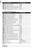
- Page 28: Parameter C10 - Select fan speeds - to set-up the speeds, press button. Function that may be associated with inputs 3, 4 and 16. No function associated. Centralised Summer/Winter function (closed contact = summer); the parameter P02 must be set to 2. Inverted centralised Summer/Winter function (closed contact = winter); the parameter P02 must be set to 2. Economy function (closed contact = reduction). Inverted economy function (contact open = reduction). Stop regulation function (closed contact = stop regulation). Inverted Stop regulation function (contact open = stop regulation). Inverted Stop adjustment function (open contact = stop adjustment).
- Page 29: Inverted Stop adjustment function (open contact = stop adjustment) the icon appears on the display. Thermostat ON / OFF function (contact closed = thermostat off). Inverted thermostat ON / OFF function (contact closed = thermostat on). Motor alarm function (contact open = alarm) - the icon appears on the display. Inverted “Motor alarm” function (contact open = alarm) - the icon appears on the display. Heating element alarm (contact closed = alarm, icons flash on the display). Inverted heating element alarm (contact open = alarm, icons flash on the display). Dirty filter warning: contact closed = dirty filter icon. Inverted dirty filter warning: contact open = dirty filter icon. Motor rpm control input (valid for input 16 only).
- Page 30: Parameter C23 - Output 8 function. No function Fan logic; relay closed when the proportional fan is on. Inverted fan logic; relay closed when the proportional fan is off. Valve logic; relay closed when the valve is open. Inverted valve logic; relay closed when the valve is closed. ON/OFF logic; the output is active when the thermostat is on. Inverted ON/OFF logic; the output is active when the thermostat is off. Economy logic; the output is active when the thermostat is in economy mode or off. Inverted Economy logic; the output is active when the thermostat is on and NOT in economy mode. Summer/Winter logic; the output is active when the thermostat is in heating (winter) mode.
- Page 31: Electrical power supply 230Vac–1Ph–50Hz JP1 Closed JP2 Open JP3 Closed JP4 Open Max= WH-RD Min= BK-RD Signal (0…10Vdc) L (Line 230V)
- Page 32: WARNING The user must set up the regulator according to his/her requirements. It is obligatory to refer to the regulator manual. Obligatory: post-ventilation. Obligatory: air speed > 1 m/s. Standard components supplied already mounted include an EC electronic fan motor. Accessories are present only if requested/ordered. The main heat exchanger valve operates at 230 V on/off. Electrical heating element operates at 230 Vac with two states. The electrical heating element cables may be connected differently based on the electrical circuit diagram. A self-rearming safety thermostat is always fitted for each state.
- Page 33: Manually re-armed safety thermostat (only upon request). Dual NO contact relay, with 230 Vac coil. Air temperature probe. Water temperature probe. Components to be supplied by the customer. The electrical system components must be selected according to the power consumption of the unit. The electrical system must be installed by a qualified technician, in accordance with all applicable standards and regulations. The system must be developed with the assistance of a professional designer. The system must be fitted with a suitable, single-pole, differential, thermo-magnetic circuit breaker. We recommend installing an additional, single-pole, fuse-protected cut-off switch upstream.
- Page 34: Page 34

Danfoss DEVIreg 530 Electronic Thermostat Installation Guide

WARMZONE UWG5 WiFi LED Touch Thermostat User Guide

Schneider SpaceLogic Thermostat Installation Guide

SIEMENS RDH100RF/SET Wireless Room Thermostat with LCD User Guide

Honeywell RTH2510 Digital 7-day Thermostat Owner’s Manual

TSTATBBEWF-01 Bryant Smart Thermostat Owner’s Manual

resideo T3 Programmable Thermostat Installation Guide

Mi-Heat GH35EU Digital Greenhouse Thermostat User Manual

tekmar TEK564 Invita WiFi Thermostat User Manual

SANGAMO CHPWIFI Fort Programmable Thermostat User Guide