Home > OLIMPIA SPLENDID > OLIMPIA SPLENDID 9899 Thermostat User Manual
×
- 1. Thermostat (Installation And User Manual)
- 2. Installation (Jumper Configuration → V~ Power Supply (factory Setting) → V~ Power Supply → Hz Frequency (factory Setting) → Parameter Setting Enabled → Parameter Setting Disabled)
- 3. Wiring Diagram (Legend → Jp2 → V Heat → V Cool → V Fan → Rdc)
- 4. Wiring Diagram For Driving 2 On-off 230 V~ Actuators In 4 Pipe Systems With Proportional Fan Drive. (Wiring Diagram For Driving 2 On-off 24 V~ Actuators In 4 Pipe Systems With Proportional Fan Drive. → Wiring Diagram For Driving A 0..10v 24 V~ Actuator For An Integrated Heating Element System And A Proportional Fan Drive. → Wiring Diagram For Driving Two 0..10v 24 V~ Actuators In 4 Pipe Systems And A 230 V Three Speed Motor.)
- 5. Pipe System With On-off Valve (Pipe System With 0..10v Servo Drive → Pipe System With Two On-off Valves → Pipe System With Two 0..10v Servo Drives → Integrated Electric Heating Element System With On-off Valve → Integrated Electric Heating Element System With 0..10v Servo Drive → Connecting A Fan To A Three Speed Motor)
- 6. Legend (Output Drive Sequences → Cooling Valve Proportional Output → Heating Valve Proportional Output → Fan Proportional Output → Heating Set-point Temperature → Cooling Set-point Temperature → Neutral Zone Amplitude)
- 7. General Information (Description Of Controls)
- 8. Button (Display Indication → Displayed Symbols → Automatic Heating/cooling Selection → Heating Element Active → Cooling Active → Temperature Regulation In 'economy' Mode)
- 9. Fan Speed Indicators (Valve Output Status → Two Pipe System → Four Pipe System → Installation)
- 10. Install (Electrical Connections)
- 11. A Window Contact May Be Connected To Terminals 14 And 16. (Change Configuration To Select The External Or Internal Sensor. → The Device May Be Used To Control Both An Electronic Fan Motor (ec Motor) And A Three Speed Fan Motor. → This Appliance Must Be Installed And Wired By Qualified Technicians And In Compliance With The Current Standards. → The Device May Be Used To Control One Or Two 0..10v Proportional Actuators Or One Or Two On/off Actuators. → Please Note That The Ground Is Electrically Connected To The Power Terminal Neutral 2.)
- 12. Technical Specifications (Power Supply → Power Consumption → Room Temperature → Regulation Range → Sensor Type → Precision → Resolution)
- 13. Pollution Rating (Tracking Index (pti) → Class Of Rating Against Electric Shock → Impulse Withstand Voltage → Operating Temperature → Storage Temperature → Weight)
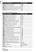
- 14. Heating/cooling Selection (Supply Water Inlet → External Inputs - Terminals 3, 4 And 16)
- 15. This Function May Be Associated With One Of These Icons:
- 16. On/off Logic (Economy Logic → Heating/cooling Logic → 10v Proportional Outputs Control → Temperature Acquisition → Minimum Temperature Thermostat Function)
- 17. System With Heating Element (System With Integrated Heating Element → Underfloor Fan Coil Heating And Cooling Systems)
- 18. Economy Function (Dirty Filter Warning Function → Temperature Regulation)
- 19. Installer Configuration (Proportional Control → Integral Action)
- 20. Reset Installer Configuration (Description Of Main Configuration Parameters → Pipe System → Pipe System → System With Heating Element → System With Integrated Heating Element → Switching Modes)
- 21. Centralised (Parameters C17, C18 And C19 → P03 And P04 → P05 → P06 And P07 → P08)
- 22. P09: Room Air De-stratification Function (P10: Thermostat State After Black-out → P11: Select Room Temperature Sensor → P12: Correcting Room Temperature Reading → P13 And P14: Set-point Temperature Range In Heating Mode → P15 And P16: Set-point Temperature Range In Cooling Mode → P17: Anti-freeze Temperature Setting)
- 23. Descriptionofextendedconfigurationparameters (C01andc02 → C03andc04 → C05andc06)
- 24. C7 And C8: Minimum Power Percentage (C09: Number Of Fan Speeds → C10: Fan Speed Selection → C11, C12 And C13: Fixed Speed Settings → C14: Minimum Speed With Electric Heater → C15 And C16: Fan Proportional Output Limits → C17, C18 And C19: Function Association With Inputs)
- 25. Correct Room Temperature Measurement (Output 8 → Main Configuration Parameters)
- 26. Description (Permitted Values → Regulate Heating → Regulate Cooling → Fan Output Type → Supply Water Inlet → Room Temperature Offset (c))
- 27. Description (Permitted Values → Fan Start Delay (seconds) → Fan Stop Delay (seconds) → Winter Supply Water Temperature Threshold (c) → Upper Changeover Threshold (c) → Heating Proportional Band (c))
- 28. Table 3: Parameter C10 - Select Fan Speeds (Table 4: Parameters C17, C18, C19 - Function That May Be Associated With Inputs 3, 4 And 16.)
- 29. Inverted 'stop Adjustment' Function ('thermostat On / Off' Function → Inverted 'thermostat On / Off' Function → 'motor Alarm' Function → Inverted 'motor Alarm' Function → Heating Element Alarm → Dirty Filter Warning)
- 30. Parameter C23 - Output 8 Function (Value → Description)
- 31. Electrical Power Supply (Electrical Section)
- 32. The User Must Set-up The Regulator According To His/her Requirements (It Is Obligatory To Refer To The Regulator Manual → Standard Components Supplied Already Mounted → Accessories (present Only If Requested/ordered))
- 33. Description (Components To Be Supplied By The Customer → N.b.:)
- 34.
×
OLIMPIA SPLENDID 9899 Thermostat User Manual
| General | Details |
|---|---|
| Name | OLIMPIA SPLENDID 9899 Thermostat User Manual |
| Make | OLIMPIA SPLENDID |
| Language | English |
| Filetype | PDF (Download) |
| File size | 5.17 MB |


network thermostat X X7-WIFI Smart Touchscreen Thermostat Instructions

BACKER ELECTRIC BMST 7 Backermatic Safety Thermostat Instructions

HERSCHEL T-MT Mains Powered WiFi Thermostat Instruction Manual

Honeywell PRO 1000 Series Non-Programmable Thermostat Instruction Manual

Roth Basicline H 230V Room Thermostat Instructions

autani SMT-131 Wireless Digital Thermostat Installation Guide

BEOK CONTROLS TDS75 Series Thermostat User Guide

Danfoss UT 72-UT 73 Universal Thermostat Installation Guide

BEOK BOT-T9N-WIFI Desktop Type RF Smart Thermostat for Wall-Hung Boiler User Manual

Price Industries Disio Display Thermostat User Guide
Table of Contents
- 1. Thermostat - Installation And User Manual →
- 2. Installation - Jumper Configuration →
- 3. Wiring Diagram - Legend →
- 4. Wiring Diagram For Driving 2 On-off 230 V~ Actuators In 4 Pi... →
- 5. Pipe System With On-off Valve - Pipe System With 0..10v Serv... →
- 6. Legend - Output Drive Sequences →
- 7. General Information - Description Of Controls →
- 8. Button - Display Indication →
- 9. Fan Speed Indicators - Valve Output Status →
- 10. Install - Electrical Connections →
- 11. A Window Contact May Be Connected To Terminals 14 And 16. - ... →
- 12. Technical Specifications - Power Supply →
- 13. Pollution Rating - Tracking Index (pti) →
- 14. Heating/cooling Selection - Supply Water Inlet →
- 15. This Function May Be Associated With One Of These Icons: →
- 16. On/off Logic - Economy Logic →
- 17. System With Heating Element - System With Integrated Heating... →
- 18. Economy Function - Dirty Filter Warning Function →
- 19. Installer Configuration - Proportional Control →
- 20. Reset Installer Configuration - Description Of Main Configur... →
- 21. Centralised - Parameters C17, C18 And C19 →
- 22. P09: Room Air De-stratification Function - P10: Thermostat S... →
- 23. Descriptionofextende... - C01andc02 →
- 24. C7 And C8: Minimum Power Percentage - C09: Number Of Fan Spe... →
- 25. Correct Room Temperature Measurement - Output 8 →
- 26. Description - Permitted Values →
- 27. Description - Permitted Values →
- 28. Table 3: Parameter C10 - Select Fan Speeds - Table 4: Parame... →
- 29. Inverted 'stop Adjustment' Function - 'thermostat On / Off' ... →
- 30. Parameter C23 - Output 8 Function - Value →
- 31. Electrical Power Supply - Electrical Section →
- 32. The User Must Set-up The Regulator According To His/her Requ... →
- 33. Description - Components To Be Supplied By The Customer →
- 34. Page 34 →


