Home > OLIMPIA SPLENDID > OLIMPIA SPLENDID 9899 Thermostat User Manual
OLIMPIA SPLENDID 9899 Thermostat User Manual


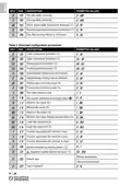


WIRING DIAGRAM
LEGEND
JP2:
Select 230/24 V~
V HEAT:
0..10 V heating signal output
V COOL: 0..10 V cooling signal output
V FAN:
HEAT:
COOL:
E/I:
0..10V fan signal output
Heating valve output
Cooling valve output
Remote input for activating the "Centralised Heating/Cooling" function
Remote input for activating the "Economy" function
Fan motor
RDC:
M:
ECM:
Sc:
Electronically commutated motor
0..10V Servo drive
S.M.:
S.A.:
CF:
Supply sensor
Room sensor
Remote input for activating the "Window contact"(*) function
Remote room temperature sensor connection. See "Electric connections"
Reinforced insulation
RS:
_ _ :
(*) The function associated with the input may be modified in parameters C17, C18 and C19.
WARNING!
The function associated with terminal 8 may be modified in parameter
C23.
IT - 2
| General | Details |
|---|---|
| Name | OLIMPIA SPLENDID 9899 Thermostat User Manual |
| Make | OLIMPIA SPLENDID |
| Language | English |
| Filetype | PDF (Download) |
| File size | 5.17 MB |


DAIKIN DKN510 Wireless VRV Communicating Thermostat Installation Guide

White-Rodgers 1F83-277 Heating & Air Conditioning Auto Changeover Heat Pump Thermostat User Manual

STELPRO STZW402+ Electronic Thermostat Owner’s Manual

AVATTO WT598 Smart Thermostat Instruction Manual

REPTITRIP HMT16N Reptile Heating Mat With Digital Thermostat User Manual

STELPRO STF362NP Floor Heating Thermostat Owner’s Manual
STELPRO UT202NP Series Non-Programmable Electric Thermostat Owner’s Manual

HBX THM-0100 Programmable Thermostat Instruction Manual

vaillant VR 92f/3 Wireless Additional Room Thermostat Instructions

DEVIreg 316 Electronic Thermostat Installation Guide