Home > OLIMPIA SPLENDID > OLIMPIA SPLENDID 9899 Thermostat User Manual
OLIMPIA SPLENDID 9899 Thermostat User Manual


A window contact may be connected to terminals 14 and 16.
N.B.:
read the paragraph “ATTENTION” for the restrictions on the use
of window contacts.
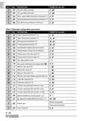
The function associated with input terminals 3, 4 and 16 may be modified in parameters C17, C18
and C19. The signals to terminals 3 and 4 may also be connected to terminals 3 and 4 of other
controllersinthesamebuilding(centralisedHeating/Coolingfunction).TheRSconnector, oralterna-
tively terminals 14 and 15, may be used to connect an external environmental temperature sensor.
Change configuration to select the external or internal sensor. Terminals 13 and 14 constitute an
input that may be used to connect different types of sensors for special functions: connect a supply
temperature sensor for the “changeover” and/or “minimum temperature thermostat” function, or a
bi-metal thermostat with “minimum temperature” function. Modify the configuration to select which
type of sensor to use (P08). The device may be used to control both an electronic fan motor (EC
motor) and a three speed fan motor. Use parameter P05 to define whether to use the 0-10V propor-
tional output for an EC motor or the three relay outputs for a three speed motor. If the proportional
output is used, the 0-10V signal will be available on terminal 11, with terminal 12 as the common
connector. Connect the EC motor as shown in Fig. 13a. When using the three relay outputs for a
three speeds motor, the outputs are available on terminals 6, 7 and 8, with terminal 5 as the common
connector. Connect the three speed motor as shown in Fig. 13b. The fan motor outputs, terminals
5 to 8, are voltage free and isolated from the rest of the thermostat with reinforced insulation. This
means that thermostat may be connected to a SELV low voltage (24 V~) power supply, but still used
to control a high voltage fan (230 V~), as shown in Fig. 10. In this case, the 24 V~ SELV and 230 V~
cables must be separated in accordance with current standards. More specifically, it is necessary
to secure the two groups of cables with cable ties so that the SELV wires are separate from the
others. This ensures that the isolation of the SELV power supply is not compromised in the event
a wire is disconnected by accident.
WARNING
This appliance must be installed and wired by qualified technicians and
in compliance with the current standards.
The device may be used to control one or two 0..10V proportional actuators or one or two ON/OFF
actuators. The outputs for the ON/OFF actuators are only available when a proportional motor is
used, i.e. when the relay outputs are not used to control the three speed motor. The heating 0..10V
proportional output is available on terminal 9, while the cooling output is available on terminal 10,
Fig.12d. In the case of two-pips systems, a single valve is used for both heating and cooling, so that
the control signal corresponds to the heating signal available on terminal 9, Fig.12b. The common
connector for all the 0..10V signals (valves and fan) is terminal 12. Please note that the ground is
electrically connected to the power terminal Neutral 2. When connecting 24 V actuators, refer to
the diagrams in Fig.9 and 10, while follow Fig. 8 refers to 230 V actuators. Usually 0..10V actuators
only have 3 connection wires, as the input signal common is connected internally to one of the two
power-supply wires (Neutral). In this case there is no need to connect terminal 12 (output signal
common), as the actuator uses the Neutral power terminal for this purpose; make sure that this
terminal is connected to terminal 2. When using ON/OFF valves, the heating output is available on
IT - 10
| General | Details |
|---|---|
| Name | OLIMPIA SPLENDID 9899 Thermostat User Manual |
| Make | OLIMPIA SPLENDID |
| Language | English |
| Filetype | PDF (Download) |
| File size | 5.17 MB |


GENERAL Life HT250 Wired Room Thermostat User Guide

Danfoss RTD 014G0251 Ally Radiator Thermostat User Guide

COPELAND 1F95G-1235GC Humidity Universal Thermostat Instruction Manual

MODINE 5-580.4 Programmable Room Thermostat Installation Guide

MCO Home MH-4936 Z Wave Thermostat Instruction Manual

HERSCHEL T-BT Battery Powered Wireless Thermostat Instruction Manual

Danfoss 014G2420 Ally Radiator Thermostat User Guide

hansgrohe AXOR UNO2 Concealed Thermostat with Shut Off Valve Instruction Manual

DOMETIC 3313192.XXX Single Zone LCD Thermostat Instruction Manual

Danfoss RT 106 Thermostat Installation Guide