Home > OLIMPIA SPLENDID > OLIMPIA SPLENDID 9899 Thermostat User Manual
×
- 1. Thermostat (Installation And User Manual)
- 2. Installation (Jumper Configuration → V~ Power Supply (factory Setting) → V~ Power Supply → Hz Frequency (factory Setting) → Parameter Setting Enabled → Parameter Setting Disabled)
- 3. Wiring Diagram (Legend → Jp2 → V Heat → V Cool → V Fan → Rdc)
- 4. Wiring Diagram For Driving 2 On-off 230 V~ Actuators In 4 Pipe Systems With Proportional Fan Drive. (Wiring Diagram For Driving 2 On-off 24 V~ Actuators In 4 Pipe Systems With Proportional Fan Drive. → Wiring Diagram For Driving A 0..10v 24 V~ Actuator For An Integrated Heating Element System And A Proportional Fan Drive. → Wiring Diagram For Driving Two 0..10v 24 V~ Actuators In 4 Pipe Systems And A 230 V Three Speed Motor.)
- 5. Pipe System With On-off Valve (Pipe System With 0..10v Servo Drive → Pipe System With Two On-off Valves → Pipe System With Two 0..10v Servo Drives → Integrated Electric Heating Element System With On-off Valve → Integrated Electric Heating Element System With 0..10v Servo Drive → Connecting A Fan To A Three Speed Motor)
- 6. Legend (Output Drive Sequences → Cooling Valve Proportional Output → Heating Valve Proportional Output → Fan Proportional Output → Heating Set-point Temperature → Cooling Set-point Temperature → Neutral Zone Amplitude)
- 7. General Information (Description Of Controls)
- 8. Button (Display Indication → Displayed Symbols → Automatic Heating/cooling Selection → Heating Element Active → Cooling Active → Temperature Regulation In 'economy' Mode)
- 9. Fan Speed Indicators (Valve Output Status → Two Pipe System → Four Pipe System → Installation)
- 10. Install (Electrical Connections)
- 11. A Window Contact May Be Connected To Terminals 14 And 16. (Change Configuration To Select The External Or Internal Sensor. → The Device May Be Used To Control Both An Electronic Fan Motor (ec Motor) And A Three Speed Fan Motor. → This Appliance Must Be Installed And Wired By Qualified Technicians And In Compliance With The Current Standards. → The Device May Be Used To Control One Or Two 0..10v Proportional Actuators Or One Or Two On/off Actuators. → Please Note That The Ground Is Electrically Connected To The Power Terminal Neutral 2.)
- 12. Technical Specifications (Power Supply → Power Consumption → Room Temperature → Regulation Range → Sensor Type → Precision → Resolution)
- 13. Pollution Rating (Tracking Index (pti) → Class Of Rating Against Electric Shock → Impulse Withstand Voltage → Operating Temperature → Storage Temperature → Weight)
- 14. Heating/cooling Selection (Supply Water Inlet → External Inputs - Terminals 3, 4 And 16)
- 15. This Function May Be Associated With One Of These Icons:
- 16. On/off Logic (Economy Logic → Heating/cooling Logic → 10v Proportional Outputs Control → Temperature Acquisition → Minimum Temperature Thermostat Function)
- 17. System With Heating Element (System With Integrated Heating Element → Underfloor Fan Coil Heating And Cooling Systems)
- 18. Economy Function (Dirty Filter Warning Function → Temperature Regulation)
- 19. Installer Configuration (Proportional Control → Integral Action)
- 20. Reset Installer Configuration (Description Of Main Configuration Parameters → Pipe System → Pipe System → System With Heating Element → System With Integrated Heating Element → Switching Modes)
- 21. Centralised (Parameters C17, C18 And C19 → P03 And P04 → P05 → P06 And P07 → P08)
- 22. P09: Room Air De-stratification Function (P10: Thermostat State After Black-out → P11: Select Room Temperature Sensor → P12: Correcting Room Temperature Reading → P13 And P14: Set-point Temperature Range In Heating Mode → P15 And P16: Set-point Temperature Range In Cooling Mode → P17: Anti-freeze Temperature Setting)
- 23. Descriptionofextendedconfigurationparameters (C01andc02 → C03andc04 → C05andc06)
- 24. C7 And C8: Minimum Power Percentage (C09: Number Of Fan Speeds → C10: Fan Speed Selection → C11, C12 And C13: Fixed Speed Settings → C14: Minimum Speed With Electric Heater → C15 And C16: Fan Proportional Output Limits → C17, C18 And C19: Function Association With Inputs)
- 25. Correct Room Temperature Measurement (Output 8 → Main Configuration Parameters)
- 26. Description (Permitted Values → Regulate Heating → Regulate Cooling → Fan Output Type → Supply Water Inlet → Room Temperature Offset (c))
- 27. Description (Permitted Values → Fan Start Delay (seconds) → Fan Stop Delay (seconds) → Winter Supply Water Temperature Threshold (c) → Upper Changeover Threshold (c) → Heating Proportional Band (c))
- 28. Table 3: Parameter C10 - Select Fan Speeds (Table 4: Parameters C17, C18, C19 - Function That May Be Associated With Inputs 3, 4 And 16.)
- 29. Inverted 'stop Adjustment' Function ('thermostat On / Off' Function → Inverted 'thermostat On / Off' Function → 'motor Alarm' Function → Inverted 'motor Alarm' Function → Heating Element Alarm → Dirty Filter Warning)
- 30. Parameter C23 - Output 8 Function (Value → Description)
- 31. Electrical Power Supply (Electrical Section)
- 32. The User Must Set-up The Regulator According To His/her Requirements (It Is Obligatory To Refer To The Regulator Manual → Standard Components Supplied Already Mounted → Accessories (present Only If Requested/ordered))
- 33. Description (Components To Be Supplied By The Customer → N.b.:)
- 34.
×
OLIMPIA SPLENDID 9899 Thermostat User Manual
INSTALLATION
4
1
2
1
2
Fig. 1
Fig. 4
5
1
3
Fig. 5
6
7
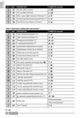
JUMPER CONFIGURATION
Installtheelectricalconnectionsinaccord-
ance with the appropriate wiring diagram
(page3)andthepossiblevariants(page4);
read the "electrical connections" para-
graph carefully.
JP2
JP4
1
8
1
Alimetazione 230V~ (impostazione di fabbr
JP1
JP2
230 V~ power supply (factory setting)
230V~ power supply (factory setting)
Alimetazione 24V~
24 V~ power supply
24V~ power supply
JP1
JP2
Frequenza 50Hz (impostazione di fabbrica)
JP3
JP4
50Hz frequency (factory setting)
JP3
JP4
Frequenza 60Hz
60Hz frequency
60Hz frequency
Configurazione parametri abilitata
JP5
Parameter setting enabled
Parameter configuration enabled
Configurazione parametri disabilitata
JP5 Parameter setting disabled
2
Parameter configuration disabled
Fig. 7
3
IT - 1
| General | Details |
|---|---|
| Name | OLIMPIA SPLENDID 9899 Thermostat User Manual |
| Make | OLIMPIA SPLENDID |
| Language | English |
| Filetype | PDF (Download) |
| File size | 5.17 MB |


Pro1 Technologies T855iSH Wall Thermostat Instruction Manual

terneo v3G33 Simple Heat Control Thermostat Instruction Manual

Honeywell TC500A-N Commercial Thermostat User Guide

LAE AC1-2W Digital Thermostat Instruction Manual

SALUS BTR230 Room Thermostat User Guide

SIEMENS RDG400 Room Thermostat Instruction Manual

AXOR 17716090 CARLTON Highflow Thermostat Instruction Manual

DAIKIN IM 1368 Vertical Stack WSHP Thermostat Instruction Manual

GENERAL LIFE NORA 270S Smart Digital Room Thermostat Instruction Manual

Honeywell CT87N Heat-Cool Round Non Programmable Thermostat Owner’s Manual
Table of Contents
- 1. Thermostat - Installation And User Manual →
- 2. Installation - Jumper Configuration →
- 3. Wiring Diagram - Legend →
- 4. Wiring Diagram For Driving 2 On-off 230 V~ Actuators In 4 Pi... →
- 5. Pipe System With On-off Valve - Pipe System With 0..10v Serv... →
- 6. Legend - Output Drive Sequences →
- 7. General Information - Description Of Controls →
- 8. Button - Display Indication →
- 9. Fan Speed Indicators - Valve Output Status →
- 10. Install - Electrical Connections →
- 11. A Window Contact May Be Connected To Terminals 14 And 16. - ... →
- 12. Technical Specifications - Power Supply →
- 13. Pollution Rating - Tracking Index (pti) →
- 14. Heating/cooling Selection - Supply Water Inlet →
- 15. This Function May Be Associated With One Of These Icons: →
- 16. On/off Logic - Economy Logic →
- 17. System With Heating Element - System With Integrated Heating... →
- 18. Economy Function - Dirty Filter Warning Function →
- 19. Installer Configuration - Proportional Control →
- 20. Reset Installer Configuration - Description Of Main Configur... →
- 21. Centralised - Parameters C17, C18 And C19 →
- 22. P09: Room Air De-stratification Function - P10: Thermostat S... →
- 23. Descriptionofextende... - C01andc02 →
- 24. C7 And C8: Minimum Power Percentage - C09: Number Of Fan Spe... →
- 25. Correct Room Temperature Measurement - Output 8 →
- 26. Description - Permitted Values →
- 27. Description - Permitted Values →
- 28. Table 3: Parameter C10 - Select Fan Speeds - Table 4: Parame... →
- 29. Inverted 'stop Adjustment' Function - 'thermostat On / Off' ... →
- 30. Parameter C23 - Output 8 Function - Value →
- 31. Electrical Power Supply - Electrical Section →
- 32. The User Must Set-up The Regulator According To His/her Requ... →
- 33. Description - Components To Be Supplied By The Customer →
- 34. Page 34 →


