Home > OLIMPIA SPLENDID > OLIMPIA SPLENDID 9899 Thermostat User Manual
OLIMPIA SPLENDID 9899 Thermostat User Manual


The “fan speed” symbols indicate the fan status: when they are all extinguished, it indicates that
the fan is off, whereas when they are illuminated it indicates that the fan is on, according to the
following indications:
Speed 1
-
speed 2
-
speed 3
If the controller is configured to control the fan via the 0..10V proportional output, the higher the fan
speed, the more fan dashes will be displayed in the fan symbol.
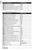
The symbols and
type of system.
indicate the status of the valve outputs, which varies depending on the
Two pipe system:
System with heating element:
heating mode, valve open
cooling mode, valve open
Four pipe system:
heating valve open
cooling valve open
heating mode, heating element on
cooling mode, cooling valve open
System with integrated heating element:
heating mode, valve open
cooling mode, valve open
heating mode, heating element on
The symbols associated with a proportional valve output are displayed even if the proportional valve
is set to a minimum opening position.
The symbols may also flash, indicating that the corresponding output should be on, but is temporarily
disabled by another function.
For example, the outputs are disabled in the following situations:
- The minimum temperature thermostat function is inhibiting the fan;
- The window contact has suspended temperature regulation.
INSTALLATION
To install the device, proceed as follows, with reference to the figures on page 1:
1. Release the plate attached to the controller base by pushing it to the left and releasing the teeth
shown in the figure.
2. Push the plastic tab in the lower slot using a screwdriver, raising the cover slightly.
3. Rotate the cover, while pressing it gently, until it is fully extracted.
4. Secure the plate to the wall, using the two screw holes with pitch distances of 60 mm or 85 mm
(usethewallplugsand/orscrewssupplied), andfeedthewiresthroughtherectangularopenings.
5. - Attach the controller base to the wall plate (passing the wires through the rectangular open-
ings), first making sure the holes on the base are aligned with the corresponding teeth on
the wall plate, and then pressing the base to the left so the plastic teeth on the plate click into
place.
-
Secure the controller base to the wall using the screw provided.
6. If necessary, configure the jumpers JP1, JP2, JP3, JP4 and JP5. Read carefully “JUMPER
SELECTION” (page 5) and “ELECTRICAL CONNECTIONS” paragraphs.
IT - 8
| General | Details |
|---|---|
| Name | OLIMPIA SPLENDID 9899 Thermostat User Manual |
| Make | OLIMPIA SPLENDID |
| Language | English |
| Filetype | PDF (Download) |
| File size | 5.17 MB |


SALUS Wired Digital Thermostat – Non-programmable HTRS230 User Manual

sinop TH1500ZB Smart Double Pole Thermostat User Guide

GENERAL LIFE ARUNA 301S Digital Room Thermostat User Manual

marmony MTC-40 Radio Controlled Room Thermostat Instruction Manual

STELPRO STE241 Low Voltage Electronic Thermostat User Guide

eurotherm Smart One 365 Thermostat User Manual

beca BAC-005 Series Thermostat User Guide

Danfoss RET230P Electronic Thermostat Instruction Manual

GENERAL SENNA 270 Smart Room Thermostat User Manual

Wengart TP808 Wi-Fi Low Voltage Thermostat User Guide