Home > Pro1 Technologies > Pro1 Technologies T855iSH Wall Thermostat Instruction Manual
Pro1 Technologies T855iSH Wall Thermostat Instruction Manual
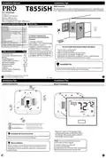
Installation Manual
Installation Tips
Wall Locations
The thermostat should be installed approximately 4 to 5 feet above the
floor. Select an area with average temperature and good air circulation.
T855iSH
Pro1 Technologies
P.O. Box 3377
Springfield, MO 65808-3377
Toll Free: 888-776-1427
Hours of Operation: M-F 9AM - 6PM Eastern
Thermostat Application Guide
Power Type
Hardwire (Common Wire)
Description
Gas or Oil Heat
Yes
Yes
Yes
Electric Furnace
Heat Pump (No Aux. or Emergency Heat)
Heat Pump (With Aux. or Emergency Heat)
Multi-Stage Systems
Yes
Yes
Yes
Yes
A trained, experienced
technician must install this
product.
Heat Only Systems
Cool Only Systems
Millivolt
No
Yes
Wired Remote Sensing
Carefully read these
instructions. You could damage
this product or cause a
hazardous condition if you fail
to follow these instructions.
Any HVAC system up to 5H/3C with
standard low voltage controlled humidifier.
Yes
Yes
Any HVAC system up to 5H/3C with standard
low voltage controlled de-humidifier.
Do not install thermostat in these locations:
• Close to hot or cold air ducts
• That are in direct sunlight
• With an outside wall behind the thermostat
• In areas that do not require conditioning
• Where there are dead spots or drafts (in corners or behind doors)
• Where there might be concealed chimneys or pipes
Table of Contents
Page
Una version en espanol de este
manual se puede descargar en
la pagina web de la compania.
Installation Tips
Thermostat Quick Reference
Wiring
Wiring Diagrams
Technician Setup Menu
WIFI Tech Settings
Setting Humidity
Programming
2-4
5-8
9-10
11-14
15-33
34
35-37
38-43
44
45
46
Installation Tip
Features
Remote Sensor Operation
Specifications
Pick an installation location that is easy for the user to access. The temperature
of the location should be representative of the building.
U.S. Registered Trademark. Patents pending
Copyright 2020 All Rights Reserved.
1
2
Rev. 2028
Installation Tips
Installation Tips
Subbase Installation
Mount Thermostat
For horizontal mount put one screw on
the left and one screw on the right.
Horizontal Mount
Vertical Mount
For vertical mount put one screw on
the top and one screw on the bottom.
Align the 4 tabs on the subbase with
corresponding slots on the back of the
thermostat, then push gently until the
thermostat snaps in place.
Installation Tip: Electrical Hazard
Failure to disconnect the power before beginning to install this product
can cause electrical shock or equipment damage.
Note: To ensure a solid fit between the
thermostat and the subbase:
Mercury Notice
1. Mount subbase to a flat wall
2. Use screws provided
3. Drywall anchors should be flush with the wall
4. Wires should be pushed into the wall
All of our products are mercury free. However, if the product you are
replacing contains mercury, dispose of it properly. Your local waste
management authority can give you instructions on recycling and
proper disposal.
4
| General | Details |
|---|---|
| Name | Pro1 Technologies T855iSH Wall Thermostat Instruction Manual |
| Make | Pro1 Technologies |
| Language | English |
| Filetype | PDF (Download) |
| File size | 0.59 MB |

Pro1 Technologies Pro1 T701i WiFi Thermostat Installation Guide

Pro1 Technologies T751 Non-Programmable Digital Thermostat Instruction Manual

Pro1 Technologies T855iSH Wall Thermostat Instruction Manual Overview
Summary of Contents
- Page 1: Installation tips include selecting a location approximately 4 to 5 feet above the floor with average temperature and good air circulation. A trained, experienced technician must install this product. Carefully read these instructions to avoid damaging the product or causing hazardous conditions. Do not install the thermostat close to hot or cold air ducts, in direct sunlight, or in areas that do not require conditioning. Pick an installation location that is easy for the user to access and representative of the building's temperature. For horizontal mount, use one screw on the left and one on the right; for vertical mount, use one screw on the top and one on the bottom. Disconnect the power before beginning installation to prevent electrical shock or equipment damage. Ensure a solid fit between the thermostat and the subbase by following proper mounting procedures. All products are mercury free, but if replacing a product that contains mercury, dispose of it properly. Refer to the installation manual for specific wiring diagrams and technician setup menu.
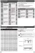
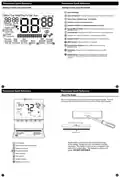
- Page 2: Thermostat Quick Reference Getting to know your thermostat Setpoint indicator displays the user selectable setpoint temperature. Indicates current room temperature. Indicates if heating or cooling equipment is running. Energy efficient globe indicates the setpoint temperature chosen is an efficient choice. Hold indicator displayed when the thermostat is in permanent hold. Keypad lockout indicates the thermostat is in keypad lockout. WIFI indicator indicates if WIFI is connected. Fan button changes the fan operation between Auto, IAQ, and On. System button changes the system operation between Off, Cool, Auto, Heat, and Emergency Heat based on system tech setting.
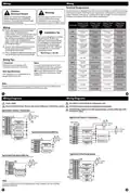
- Page 3: Wiring Terminal designations This thermostat is shipped from the factory to operate a conventional heating and cooling system. This thermostat may also be configured for a heat pump system. Caution: Electrical hazard All components of the control system and the thermostat installation must conform to Class II circuits per the NEC Code. Failure to disconnect the power before beginning to install this product can cause electrical shock or equipment damage. Do not overtighten terminal block screws, as this can damage the terminal block. This thermostat requires a 24V common wire to the C terminal. Use shielded or non-shielded 18-22 gauge thermostat wire. A 24V AC common connection is required with this thermostat.
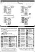
- Page 4: Wiring diagrams are essential for connecting the thermostat properly. A 24V AC common connection is required with this thermostat. Factory-installed jumper should be removed only when installing on 2 transformer systems. Use either O or B terminals for changeover valve. If the dehumidify relay requires a normally-energized input, set the dehumidify relay to NC in Technician Setup. The thermostat has a technician setup menu for easy installer configuration. The heating swing setting is adjustable from 0.2˚ to 2˚. Press the MENU button and hold the TECH SET button for 3 seconds to access the technician setup. The cooling swing setting is adjustable from 0.2˚ to 2˚. This feature allows the installer to change the calibration of the room temperature display.
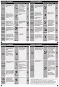
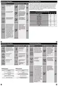
- Page 5: Technician Setup Menu Tech setup steps allow for adjustment options. This setting allows you to select the number of heat and cool stages. Staging is satisfied when multiple stages of heat or cool are energized until the setpoint is reached. This feature allows a delay if an additional stage is needed. You can set the minimum compressor run time to “OFF”, “3”, “4”, or “5” minutes. Keypad lockout allows you to configure the thermostat so some or all of the keys don’t function. You can configure this thermostat to have a 7-day program or no program. Keypad lockout with code shows only when set to BASIC, PARTIAL, or FULL. This feature will start heating and cooling early to bring the building temperature to its programmed setpoint. This setting maximizes efficiency and equipment longevity by increasing the heating and cooling swing settings.
- Page 6: Technician Setup Menu Tech setup steps Keypad lockout with code creation is displayed when keypad lockout code is turned on. This feature allows you to display temperatures in either Fahrenheit or Celsius. You can select either a 12 or 24 hour clock setting. The pre-occupancy fan settings will energize the fan before the occupied time to provide ventilation prior to scheduled occupancy time periods. The master code will override any created keypad lock code. This feature allows you to set a maximum heating setpoint limit. This feature allows you to set a minimum cooling setpoint limit. This feature will select a temporary hold time frame for the programmable mode of the thermostat. This setting selects the minimum number of minutes that the fresh air damper will be energized.
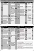
- Page 7: Technician Setup Menu Tech Setup Steps You can disable the sensor on the T855SH thermostat. Fresh Air Mode allows fresh air into a unit for a selectable amount of time. Local Temp Sensor OFF: Thermostat does not enable Fresh Air Mode. OC ON: Fresh Air Mode is enabled during the OCCUPIED, WAKE, RETURN, and SLEEP time periods. You can configure the thermostat for one of three remote sensor applications: 0 No Sensor, 1 Indoor, 2 Outdoor, 3 Floor. Balance point with electric auxiliary will optimize heat pump usage. This setting provides the option to select a terminal for Free Cooling functions. Heat will be locked out when the floor temperature is above the maximum floor temperature limit. This feature will bring in outside air for first stage cooling operations if the outdoor temperature is 5 degrees lower than the setpoint temperature.
- Page 8: Technician Setup Menu Tech Setup Steps Adjustment Options This table references different humidity levels the thermostat will conform to, based on the outdoor temperature measurements. When the Automatic Humidity Adjusting tech setting selection is ON1 or ON2, the thermostat humidity will stay adjusted to the humidity level that corresponds to the outdoor temperature. This feature adds humidity when the system key is in HEAT. This feature removes humidity when the system key is in COOL. This feature allows the installer to change the calibration of the ambient humidity displayed. The A/C will “over cool” the room a few degrees until humidity reaches the desired setpoint. Summer Away Mode protects the home in unoccupied long periods of time, during hot and humid weather. Cycle Minimizer is turned ON when Summer Away Mode is activated by the user. DHM terminal energizes when the ambient humidity is above the humidity setpoint and cool or fan is energized.
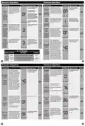
- Page 9: Technician Setup Menu These steps/options are only used for troubleshooting, resetting, or restoring to default the WIFI settings of the thermostat. They are not needed for installation or initial setup. This tech setting will select the desired humidity level for Summer Away Mode. Use the + or - keys to change settings and the NEXT or PREV key to move from one step to another. The thermostat will default to the Dehumidify set point when Summer Away Mode is turned “ON.” If ON is selected, the ambient temperature will operate off of a combination of the air temperature and the relative humidity. The thermostat will show the comfort index in the ambient temperature area and drive the heating and cooling based on this. The target humidity setpoint is not programmable. Unlike temperature, humidity does not change quickly and should not be programmed. Humidity is only energized during heat. Dehumidify is only energized during cool. Heat and Cool each have their own target setpoints.
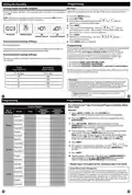
- Page 10: Programming Setting the humidity Setting target humidity setpoint Follow the steps below to set the day of the week and current time. Press the MENU button. The current hour is flashing. Use the key to select the current hour. When using 12-hour time, make sure the correct a.m. or p.m. choice is selected. Recommended heating settings: Increasing humidity Your thermostat can be programmed to have each day of the week programmed uniquely. This thermostat has a programmable fan feature, which allows you to run the fan continually during any time period. To customize your 7 day 4 time period program schedule, follow these steps.
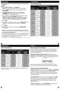
- Page 11: Programming To customize your 7 day 2 time period program schedule, follow these steps. Default Programming Factory Default Program Select HEAT or COOL with the SYSTEM key. You have to program heat and cool each separately. Press the MENU button. Time is flashing. Use the or key to make your time selection for that day’s OCCUPIED time period. The setpoint temperature is flashing. Use the to make your setpoint selection for that day’s OCCUPIED or UNOCCUPIED period. Repeat steps 4 through 7 for that day’s UNOCCUPIED time period. The programmable fan feature will run the fan continuously during any time period it is programmed to be on. If the filter change reminder is enabled, you will see a reminder in the display when your air filter needs changed.
- Page 12: Remote sensor operation The display range of temperature is 41˚F to 95˚F (5˚C to 35˚C). The control range of temperature is 44˚F to 90˚F (7˚C to 32˚C). Load rating is 1 amp per terminal, 1.5 amp maximum all terminals combined. Swing (cycle rate or differential) for heating is adjustable from 0.2˚ to 2.0˚ and for cooling from 0.2˚ to 2.0˚. Power source is 18 to 30 VAC, NEC Class II, 50/60 Hz for hardwire. Operating ambient is 32˚F to +105˚F (0˚C to +41˚C). Operating humidity is 90% non-condensing maximum. Dimensions of thermostat are 4.7”W x 4.3”H x 0.9”D. Frequency range is 2.4 GHz ISM radio band. WIFI supports 802.11 B/G/N standards.