Home > SALUS > SALUS RT310SR Wireless Thermostat User Manual

SALUS RT310SR Wireless Thermostat User Manual

RT310SR THERMOSTAT - FULL USER MANUAL  
GeneralDetails
NameSALUS RT310SR Wireless Thermostat User Manual
MakeSALUS
LanguageEnglish
FiletypePDF (Download)
File size0.6 MB
Download PDF
1 Star2 Stars3 Stars4 Stars5 Stars (1 votes, average: 5.00 out of 5)
Loading...
SALUS IT800 WIFI Smart Thermostat Installation Guide
SALUS 091FLRF Wireless Room Thermostat User Guide
SALUS Thermostat Sensor TS600 User Guide
SALUS Thermostat and Smart Plug Installation Guide
SALUS Programmable Wired Thermostat VS30W/VS30B Installation Guide
SALUS Wired Thermostat Installation Guide
SALUS Wired Digital Thermostat – Non-programmable HTRS230 User Manual
SALUS RT520 Radiator Thermostat User Guide
SALUS RT310 Thermostat User Manual
SALUS Thermostat RT520 User Manual

SALUS RT310SR Wireless Thermostat User Manual
Get the free PDF manual for the SALUS RT310SR Wireless Thermostat User Manual and access setup steps, usage instructions, and troubleshooting tips. 👉 View online or download now to keep your thermostat running smoothly!

SALUS RT310SR Wireless Thermostat User Manual Overview

Summary of Contents

  • Page 1: Page 1
  • Page 2: Introduction Product compliance Safety informations Product overview Package content Proper thermostat location Wall mounting SR868 smart relay receiver Smart relay LED indication Connection description Before you start (first power up) LCD icon description Button description First power up sequence and configuration User settings Manual mode - changing temperature setpoint Frost protection mode Sleep mode Heat/Cool mode Installer mode DIP switches parameters RT310TX thermostat pairing with the SR868 relay receiver RT310TX thermostat pairing with few other receivers Test the pairing process Reset function Cleaning and maintenance Technical informations Warranty
  • Page 3: Product overview The RT310 room thermostat switches the heating system on and off as necessary by sensing the air temperature. Turning the thermostat to a higher setting does not make the room heat up faster. The heating system will not work if a time switch or programmer has switched it off. Set the thermostat to the lowest comfortable temperature and leave it alone. Adjusting the thermostat above a comfortable setting will waste energy and increase costs. A single room thermostat typically controls the whole house, but thermostatic radiator valves (TRVs) can allow for different temperatures in individual rooms. Room thermostats need a free flow of air to function properly and should not be obstructed. Product advantages include being factory-paired and ready to work, having a TPI control algorithm, and a frost protection mode. The thermostat features a HOLIDAY mode and SLEEP mode for energy savings. It operates at 868 MHz, providing a stable and noise-resistant signal.
  • Page 4: Wall mounting Content used for thermostat mounting How to mount the thermostat to the wall: Fix the backplate to the wall. Align the front housing at the top edge. Fit the front housing. Press lightly.
  • Page 5: SR868 smart relay receiver provides control of electrical heating and must be used with wireless RT series thermostats. The thermostat communicates wirelessly with the SR868 smart plug receiver, which requires a supply of 230VAC and has a maximum load of 16A. Installation should avoid areas directly exposed to water, moisture, and air condensation. The smart relay receiver features an LED diode that indicates various states. The LED states include: - On: The relay is off. - Red flash: The relay is in pairing mode or on. - Green on: The relay is writing pairing code or paired but lost link. - Flashing indicates software version after reboot. Different sequences of red and green flashes also convey specific information.
  • Page 6: Connection description includes AC 230V specifications. The RT310TX device is referenced with connections for L, COM, and NO. The power supply is indicated as 230V with L and N symbols. Voltage-free output is described with COM and NO. The document mentions a fuse in the connection setup. There is a boiler connection noted for the boiler’s contacts for ON/OFF thermostat. Instructions for the boiler's thermostat are referenced. The device operates with a power supply of 3V using 2 x AA batteries. The legend provides explanations for the symbols used in the document. Electric heater specifications are included in the connection description.
  • Page 7: Before you start (first power up) LCD icon description Heating mode indication Cooling mode / Frost protection mode indication Low battery status Temperature unit Room / setpoint temperature RF signal indicator (only in RT310RF) Button description Turn on the LCD backlight
  • Page 8: First power up sequence and configuration To power up the thermostat, you have to put the batteries inside. Remove the protection foil and insert 2xAA batteries by removing the front cover. After that, the thermostat will automatically power up and display all icons. Then the thermostat will display the software version. When the thermostat is successfully powered up, the main screen will be displayed.
  • Page 9: User settings Manual mode - changing temperature setpoint In manual mode, the thermostat maintains a constant temperature set by the user. To set temperature setpoint follow steps below: Press or to set the new temperature setpoint. First, thermostat is displaying actual room temperature. Now wait 2 seconds timeout to approve the changes. Thermostat will display main screen (actual room temperature).
  • Page 10: Frost protection mode automatically sets the temperature to prevent pipes from freezing. If the room temperature is below the frost setpoint, frost protection is enabled. To set frost protection mode, press the button to turn it ON/OFF. The snowflake icon indicates that frost protection is active. The frostpoint temperature can be reviewed but only changed in Installer Mode. Frost protection mode can only be enabled in HEAT mode. In sleep mode, the thermostat is switched off and does not consume energy. To activate sleep mode, press and hold the buttons simultaneously for 3 seconds. In sleep mode, the thermostat displays nothing. To deactivate sleep mode, press any button to return to the main screen.
  • Page 11: Heat/Cool mode allows the user to set the thermostat for heating or cooling. In HEAT mode, the thermostat displays a flame icon continuously. When calling for heat, the flame icon flashes. In COOL mode, the thermostat displays a snowflake icon continuously. When calling for cool, the snowflake icon flashes. The default mode is HEAT mode. There is a delay of about 3 minutes when the thermostat needs to start calling for cooling. To set the cooling mode, press and hold the snowflake button for 5 seconds. The snowflake icon will be steady ON when in cooling mode. To set the heating mode, press and hold the snowflake button for 5 seconds. The flame icon will be steady ON when in heating mode. This function is available only from firmware version 2.1.
  • Page 12: Installer mode allows access to installer parameters. To enter installer mode, press and hold specific buttons simultaneously for about 3 seconds. Use the navigation button to move through parameters and confirm changes with the designated button. A detailed table with all installer parameters is provided. Temperature display accuracy can be set to 0.1°C or 0.5°C, with a temperature offset range of +/- 3.0°C. Frost protection setpoint temperature ranges from 5.0°C to 17.0°C. DIP switches are located under the back cover of the thermostat to set the control algorithm. The position of DIP switches determines the type of control algorithm for cooling and heating. The TPI algorithm is recommended for underfloor heating, adjustable between 6 CPH and 9 CPH. CPH refers to cycles per hour, indicating the frequency of measurement cycles performed by the thermostat.
  • Page 13: RT310TX thermostat pairing with the SR868 relay receiver The word pairing in the user settings means the function of synchronizing the transmitter with the receiver again, if it has been removed. In the set RT310SR the thermostat is factory paired with the SR868 receiver. In order to pair the devices correctly, you must first prepare the receiver for synchronization. Connect the receiver to a 230V power supply. Press and hold the button. After 5 seconds, the red LED will flash, which means the SR868 relay is ready to pair with the thermostat. Press and hold TEST / PAIRING button for 3 seconds. It can take up to 9 minutes. When the red diode on the receiver lights up continuously, the devices have been paired on a new frequency. Forcing the pairing process will generate a new communication code. The thermostat will go back to the main screen and it has been paired successfully.
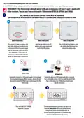
  • Page 14: RT310TX thermostat pairing with other receivers The word pairing in the user settings means the function of synchronizing the transmitter with the receiver again, if it has been removed. If the thermostat is already paired with any receiver, you will have to pair it again with other receivers. You can pair a few receivers with one thermostat RTRX510, SPE868, and SR868. Prepare all the receivers you want to pair with the thermostat. The preparation of the receivers for the pairing process is confirmation of the red LED flashing on them. If you want to re-pair the devices, make sure that the receiver is disconnected from the power supply and the switches on it are in the AUTO and ON positions. The red LED will start blinking, which will confirm that the receiver has entered the pairing mode. Press and hold the button for the SR868 relay or SPE868 plug for 5 seconds to indicate readiness to pair with the thermostat. Press and hold the TEST / PAIRING button for 3 seconds to start the pairing process. Forcing the pairing process will generate a new communication code, deleting all previously paired receivers from the thermostat's memory.
  • Page 15: After a successful pairing, the receiver’s LEDs will glow constantly red. Press and hold the TEST / PAIRING button for 3 seconds to end the pairing process. The thermostat will go back to the main screen and it has been paired successfully.
  • Page 16: Test the pairing process It is important to place the receiver and transmitter in places where nothing interferes with the radio signal. The range of communication between the transmitter and the receiver in an open area is up to 60m. The radio transmission is influenced by many factors that can shorten the working distance, such as thick walls, drywall covered with aluminum foil, and metal objects. It is recommended to test the radio transmission between devices before mounting the regulator on the wall. The test can be performed by changing the set temperature, i.e., by activating or deactivating the heating. Press the TEST / PAIRING button to check the connection with the receiver. The green LED on the SR868 smart plug receiver will begin to flash. Test mode can take up to 9 minutes. Press the TEST / PAIRING button again to return to the main screen. If you purchased an SR868 or RT310TX and intend pairing with other devices in the 5x5 range, please refer to the Receiver Units manual.
  • Page 17: Reset function To reset the RT310 thermostat, follow the steps below. When changing the batteries, the device will use the internal memory to backup your settings. You have 30 seconds to change the batteries before losing your settings. Remove the batteries without pressing any button. Wait 2 minutes and insert the batteries again. Your device will be restarted.
  • Page 18: Cleaning and maintenance require no special procedures. The outer casing can be wiped clean with a dry cloth. Avoid using solvents, polishes, detergents, or abrasive cleaners. There are no user serviceable parts within the unit. Servicing or repairs should be carried out by Salus Controls or their appointed agents. Transmitter’s power supply is 2 x AA batteries. Receiver’s power supply is 230V AC 50 Hz. The maximum rating is 16 (5) A. The output signal is NO/COM relay. The temperature range is 5 - 35°C. Display temperature accuracy is 0.1°C or 0.5°C. The control algorithm is TPI or Hysteresis: 0.25°C. Communication operates at 868Mhz. Dimensions for the transmitter are 96 x 96 x 27 mm and for the receiver are 44 x 44 x 26 mm.
  • Page 19: Warranty SALUS Controls warrants that this product will be free from any defect in materials or workmanship, and shall perform in accordance with its specification, for a period of five years from the date of installation. SALUS Controls' sole liability for breach of this warranty will be (at its option) to repair or replace the defective product.
  • Page 20: Page 20
  • Page 21: Importer: QL Controls Sp. z o.o. Sp. k. Producer: Salus Limited SALUS Controls is a member of the Computime Group. Maintaining a policy of continuous product development, SALUS Controls plc reserves the right to change specification, design, and materials of products listed in this brochure without prior notice. Ver. 2 Issued: 27 I 2021 Soft version: 2.1