SIEMENS TH 193 HC Heating and Cooling Room Thermostat Instruction Manual


Technical Instructions
Document No. 155-068P25
TH 193-4
February 14, 2022
POWERS™ CONTROLS
Free Energy Band® TH 193 HC
Heating/Cooling Room Thermostat
Description
The TH 193 HC thermostats are proportional, dual output, dual setpoint, two-pipe (dual
one-pipe, low air capacity) or three-pipe (dual two-pipe, high air capacity) sensor
controllers. Each thermostat includes a wall mounting plate for installation in a variety of
rough-in terminal boxes. Sensitive bimetals respond to temperature changes to
modulate control air through a flapper nozzle. As the heating load decreases due to
internal heat gains, a dead band of control minimizes energy consumption while the
setpoint changes from 72°F (22C) heating mode to 78F (26C) cooling mode. Two
setpoint dials allow adjustment of the dead band 4F (2C) minimum. Air connections
are made with 5/32-inch (4 mm) O.D. plastic tubing, directly to the thermostat chassis
for retrofit applications or with plug-in adapters (provided with the TH 192 rough-in
terminal box or optional accessories), which slide into the wall mounting plate.
•
•
•
•
•
•
•
•
•
Direct and reverse acting for heating and cooling modes.
Two separate, adjustable temperature setpoint indicating dials.
Two highly sensitive bimetal thermostatic elements.
Fahrenheit or Celsius models.
Features
Individual field adjustable sensitivity with graduated scale.
Integral field adjustable limit stops.
Control pressure test port accessible without removing cover.
Easily replaceable thermometer, setpoint dials, filters and restrictor plate.
Covers available for concealed or exposed thermometers, and for concealed
adjustment and setpoint indication.
•
Standard plastic thermostat covers provide Desert Beige or white finish.
Siemens Industry, Inc.

| General | Details |
|---|---|
| Name | SIEMENS TH 193 HC Heating and Cooling Room Thermostat Instruction Manual |
| Make | SIEMENS |
| Language | English |
| Filetype | PDF (Download) |
| File size | 0.15 MB |


SIEMENS RDZ100ZB Zigbee Room Thermostat Owner’s Manual

SIEMENS RDG400 Room Thermostat Instruction Manual

SIEMENS M3182 Room Thermostat Instruction Manual

SIEMENS RDS120-B Smart Thermostat Instructions

SIEMENS Powers Controls TH 192-3 Series Day Night Vent Room Thermostat Instruction Manual

SIEMENS RDY2000BN BACnet Commercial Thermostat User Manual

SIEMENS RDH100RF/SET Room Thermostat Instruction Manual

SIEMENS RDH100RF/SET Wireless Room Thermostat with LCD User Guide

SIEMENS RS485 Flush Mounted Room Thermostat User Manual

SIEMENS RDG260KN Room Thermostat Instruction Manual

SIEMENS TH 193 HC Heating and Cooling Room Thermostat Instruction Manual Overview
Summary of Contents
- Page 1: Technical instructions for the TH 193 HC heating/cooling room thermostat are provided. The thermostat is a proportional, dual output, dual setpoint controller suitable for various piping systems. It includes a wall mounting plate for installation in different terminal boxes. Sensitive bimetals modulate control air based on temperature changes. A dead band of control minimizes energy consumption as the heating load decreases. Two setpoint dials allow for adjustment of the dead band. Air connections can be made with plastic tubing or plug-in adapters. The thermostat features direct and reverse acting modes for heating and cooling. It includes individual field adjustable sensitivity and integral limit stops. Control pressure test port is accessible without removing the cover.
- Page 2: Technical instructions for the Free Energy Band TH 193 HC heating/cooling room thermostat are provided. Fixed temperature limit stops meet government specifications. Metal covers are available in standard configurations with a Desert Beige finish. TH 193 HC thermostats control space temperature and utilize the dead band to maintain energy management and occupancy comfort. These thermostats control valve and damper actuators in applications requiring early morning heat and afternoon cooling. Two-pipe thermostats are used with external restrictors for limited air capacity, while three-pipe thermostats are for higher air capacities. The thermostats can have covers that either conceal or expose the setpoint adjustment dials.
- Page 3: Free Energy Band TH 193 HC Heating/Cooling Room Thermostat Technical Instructions Document Number 155-068P25 See Table 1 for product number and ordering information on TH 193 HC thermostat. Does the application require a one-pipe or two-pipe connection? One-pipe thermostats are low air capacity devices and have only one port connection (R1). This application requires an external restrictor. Two-pipe thermostats are high air capacity devices for controlling two or more terminal devices such as damper actuators or valves. This application requires two port connections: supply (S) and return (R1). Is a Fahrenheit or Celsius scale required? Is the heating control direct or reverse acting? Is the cooling control direct or reverse acting?
- Page 4: Technical instructions for the Free Energy Band TH 193 HC heating/cooling room thermostat are provided. The document includes product number and ordering information for the TH 193 HC thermostat covers. Key considerations include whether the setpoint adjustment, thermometer, and setpoint indication are exposed or concealed. Different cover materials are available, including plastic and zinc cast metal. The standard finish color for covers is Desert Beige, with an option for white plastic covers. A table outlines the part numbers for various cover configurations. Specific configurations include options for setpoint adjustment, thermometer, and indicator visibility. A key setpoint adjustment cover is required for thermostat chassis with optional setpoint adjustment knobs. Instructions for ordering a plastic cover with a white finish are included. The document is dated February 14, 2022.
- Page 5: Free Energy Band TH 193 HC Heating/Cooling Room Thermostat Control action Specifications Operating ranges: 45°F to 85°F (7°C to 30°C) Supply air pressure, maximum: 30 psi (207 kPa) Sensitivity adjustment: 1 to 4 psi/°F (12 to 50 kPa/°C) Temperature response: 0.1°F (0.06°C) Storage temperature: -10°C to 140°F (-23°C to 60°C) The TH 193 HC thermostat is a two-temperature thermostat with two separate outputs. In direct acting control, an increase in temperature increases the control air pressure. The TH 193 HC provides two separate bimetal elements; one for heating mode and the other for cooling mode.
- Page 6: Technical instructions for the Free Energy Band TH 193 HC heating/cooling room thermostat are provided. The document includes operating characteristics and input/output characteristics of the thermostat. Thermostat details are illustrated in the figures. A test thermometer should be used to read the current room temperature. Calibration of the thermometer involves adjusting the thermometer assembly with a screwdriver. Care should be taken to avoid breathing on or touching the bimetal spiral, as it affects the temperature reading.
- Page 7: Free Energy Band TH 193 HC Heating/Cooling Room Thermostat Limit stop adjustment defines the minimum and maximum thermostat setpoints. To change limit stop settings, use needle nose pliers to pull the limit stop between the setpoint cam gear teeth. Changing the limit stop position one gear tooth changes the limit stop setting by 1-1/3°F (0.7°C). To change thermostat sensitivity, use a flat-blade screwdriver to carefully move the sensitivity slide to the desired position. If the thermostat sensitivity is adjusted, the thermostat must be recalibrated. The thermostat is factory-calibrated to a control pressure of 7.5 psi (52 kPa) when the setpoint and the ambient temperature are both at 72°F (22°C). The factory sensitivity setting is approximately 2.5 psi/°F (31 kPa/°C). No adjustments are required if these settings are appropriate for the application. If the thermostat has been tampered with, the sensitivity changed, or is out of adjustment, follow the steps to recalibrate the instrument.
- Page 8: Technical instructions for the Free Energy Band TH 193 HC heating/cooling room thermostat are provided. The document outlines the cooling calibration process. Step 1 involves removing the cover and verifying the supply pressure. Step 2 requires checking that the room temperature is between 70°F and 80°F. Adjust the cooling dial to the appropriate room temperature. Allow the thermostat to stand for about five minutes to adjust to the new setting. Step 3 and Step 4 detail the use of the test gauge and needle adapter. Control pressure should be read and adjusted if necessary. Calibration is achieved when the control pressure reads 7 to 8 psi. The setpoint can then be changed to the desired room temperature.
- Page 9: Free Energy Band TH 193 HC Heating/Cooling Room Thermostat Technical Instructions Heating Calibration Verify that the supply pressure is 25 psi. Verify that the room temperature is between 70°F and 80°F (21°C and 27°C). Set the heating dial to room temperature by turning the exposed adjustment knob or using a hex key. Allow the thermostat to stand for about five minutes to adjust to the new setting. Moisten the needle and insert the 192-633 Test Gauge and needle adapter in the test port. Read the control pressure. If the control pressure does not read 7 to 8 psi (48 to 55 kPa), turn the calibration screw until pressure is 7 to 8 psi (48 to 55 kPa). The sensing element is now in calibration and the setpoint can be changed to the desired room temperature.
- Page 10: Technical instructions for the Free Energy Band TH 193 HC heating/cooling room thermostat are provided. Before troubleshooting, ensure clean, dry supply air at a minimum of 18 psi (124 kPa). Use a test probe gauge and needle adapter to measure control pressure at the thermostat test port. The output pressure test port is accessible without removing the thermostat cover. For one-pipe thermostats, the port is on the right side; for two-pipe thermostats, it is on the left side. Using the wrong test port can cause thermostat damage and may require replacement. A troubleshooting guide is available to address various problems and their causes. Common issues include low supply pressure, dirt on the nozzle or flapper, and clogged restrictors. Actions may involve cleaning components or recalibrating the thermostat. Ensure supply and return line connections are correct to avoid excessive air leakage.
- Page 11: Free Energy Band TH 193 HC Heating/Cooling Room Thermostat Technical Instructions Remove the thermostat chassis from the wall. The terminal does not have a ball check valve. You must close off the supply air. Remove the two Phillips head screws from the connector on the back of the thermostat chassis. Use Restrictor Replacement Kit 192-321 to replace the gasket, restrictor, and second gasket. The restrictor plate is keyed to ensure proper orientation during installation. Remove the filters from the existing connector and insert in the new connector. Use Chassis Tube Connector Replacement Kit 192-525 to replace the connector and mounting screws.
- Page 12: Technical instructions for the Free Energy Band TH 193 HC heating/cooling room thermostat are provided. A chart lists accessory parts and tools available for thermostat service. Descriptions and part numbers for various tools and replacement kits are included. Items listed include a dial thermometer, calibration kits, test head kits, and various gauges. Replacement kits for chassis tube connectors and restrictor plates are mentioned. Plug-in adapters for quick thermostat removal are available in different colors and packages. Compression rings and elbows for wall surface mounting are also listed. Specific details about restrictors for one-pipe systems are provided. Brass couplings and tees for piping systems are included in the parts list. The document is dated February 14, 2022.
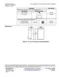
- Page 13: Technical instructions for the Free Energy Band TH 193 HC heating/cooling room thermostat are provided. The document includes part numbers for replacement thermometer kits and setpoint dials. The scale range for the thermostat is 45°F to 85°F and 10°C to 30°C. Models 1 and 2 are specified for the thermostat. Dimensions of the TH 193 HC are illustrated in a figure. The company reserves the right to make changes in specifications and models as design improvements are introduced. POWERS and Free Energy Band are trademarks of Siemens Industry, Inc. Other product or company names mentioned may be trademarks of their respective owners. Feedback on the document is encouraged. The document is printed in the USA.

ENGO CONTROLS E901RF Series Programmable Thermostat User Guide

Braeburn 8205 Universal Smart Wi-Fi Thermostat User Guide

Goldair GEPH213 EcoPanel Heater with Thermostat Instruction Manual

STN855W WiFi Digital Programmable Thermostat Instruction Manual

TSTATBBEWF-01 Bryant Smart Thermostat Owner’s Manual

KALOR TECH 603H Thermostat Instruction Manual

ETHERMA 3 set 2024 Smart Thermostat Instruction Manual

DEVIreg 610 Electronic Thermostat Installation Guide

STELPRO STE402NP Smart Electronic Thermostat User Guide

Wengart WG603 Home Smart Thermostat User Guide