SIEMENS RS485 Flush Mounted Room Thermostat User Manual


Flush-mounted room thermostat with RS485 Modbus
communications
RDF660MB/MM, RDF660MB
For 2-pipe, 2-pipe with electric heater and 4-pipe fan coil units
●
●
●
●
●
●
●
●
●
●
●
●
●
AC 230 V operating voltage
Large, backlit display
On/off or 3-position control outputs
Automatic or manual fan speed control
ECM fan DC 0...10 V output
Operating modes: Comfort, Economy and Protection
Control depending on the room or the return air temperature
Automatic or manual heating/cooling changeover
Minimum and maximum limitation of room temperature setpoint
2 inputs for external or changeover sensor, keycard or window contact
Commissioning and control parameters via local HMI or RS485 Modbus
RS485 communicative interface in Modbus RTU slave mode
User and parameter settings can be retained or restored with power loss to
previous mode, Comfort mode or Protection mode
●
Mounting on both round and square conduit boxes, 60 mm fixing centers
A6V12005486_en--_d
2022-11-14
Smart Infrastructure

| General | Details |
|---|---|
| Name | SIEMENS RS485 Flush Mounted Room Thermostat User Manual |
| Make | SIEMENS |
| Language | English |
| Filetype | PDF (Download) |
| File size | 1.07 MB |


SIEMENS RDZ100ZB Zigbee Room Thermostat Owner’s Manual

SIEMENS RDG400 Room Thermostat Instruction Manual

SIEMENS M3182 Room Thermostat Instruction Manual

SIEMENS RDS120-B Smart Thermostat Instructions

SIEMENS Powers Controls TH 192-3 Series Day Night Vent Room Thermostat Instruction Manual

SIEMENS RDY2000BN BACnet Commercial Thermostat User Manual

SIEMENS RDH100RF/SET Room Thermostat Instruction Manual

SIEMENS RDH100RF/SET Wireless Room Thermostat with LCD User Guide

SIEMENS RDG260KN Room Thermostat Instruction Manual

SIEMENS RDF660MB Flush Mount Room Thermostat Instruction Manual

SIEMENS RS485 Flush Mounted Room Thermostat User Manual Overview
Summary of Contents
- Page 1: Flush-mounted room thermostat with RS485 Modbus communications For 2-pipe, 2-pipe with electric heater and 4-pipe fan coil units AC 230 V operating voltage Large, backlit display On/off or 3-position control outputs Automatic or manual fan speed control Operating modes: Comfort, Economy and Protection Control depending on the room or the return air temperature Commissioning and control parameters via local HMI or RS485 Modbus RS485 communicative interface in Modbus RTU slave mode
- Page 2: Use applications for room temperature control in individual rooms and zones. The room thermostat controls various components including ECM fans and valve actuators. It is used in systems with heating or cooling capabilities and offers automatic or manual changeover options. The thermostat comes with a fixed set of applications that can be selected during commissioning. Key functions include maintaining room temperature, changing between heating and cooling modes, and selecting applications via DIP switches. The thermostat displays current room temperature and allows for setpoint limitations. It features a key lock and multiple freely selectable inputs for external sensors and devices. Two multifunctional inputs are available for additional sensor options. The document includes a version date and reference to Siemens Smart Infrastructure.
- Page 3: Electric heater enabled (DI) Fault input (DI) Monitor input (DI) Automatic heating/cooling changeover sensor (DI) Presence detector (DI) Hotel keycard (DI) Advanced fan control function, e.g. fan kick, fan start, selectable fan operation Purge function together with 2-port valve in a 2-pipe changeover system Reminder to clean filters Reload factory settings for commissioning and control parameters
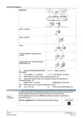
- Page 4: Equipment combinations Type of unit Product no. Data sheet Cable temperature or changeover sensor Room temperature sensor NTC Condensation monitor / Dewpoint monitor On/Off actuators Electric actuator, 3-position
- Page 5: For the maximum number of actuators in parallel, refer to information in the data sheets of the selected actuators. Parallel operation of max 6 SS… actuators (3-pos) is possible. Parallel operation of max 10 On/Off actuators is possible. Parallel operation of SQS35 is not possible. The thermostats consist of 2 parts: front panel with electronics, operating elements and built-in room temperature sensor, and mounting base with power electronics. The rear of the mounting base contains the screw terminals. The base fits on a square conduit box with 60 mm fixing centers. Slide the front panel in the mounting base and snap on. Operating mode selector, change fan operation, and adjust setpoints and control parameters are key operation and settings.
- Page 6: Operating modes include protection, comfort, and economy. Displays show room temperature, setpoints, and control parameters. A symbol indicates the current room temperature. Fan modes include auto fan active and fan speed options: low, medium, and high. Indicates fault or reminder. Heating/cooling modes include cooling, heating, and electrical heater active (RDF660MB only). Condensation in the room is indicated by the dew point sensor being active. Additional user information includes room temperature, outdoor temperature from Modbus, or time. Key lock active.
- Page 7: Product documentation Operating instructions Basic documentation CE declarations Environmental product declaration Notes Security National safety regulations The device address is assigned to “1” (factory setting). The Baud rate is selectable. Four options are available for the Modbus network.
- Page 8: Mount the room thermostat on a recessed square conduit box with 60 mm fixing centers. Do not mount on a wall in niches or bookshelves, behind curtains, above or near heat sources, or exposed to direct solar radiation. Mount about 1.5 m above the floor in a clean, dry indoor place without direct airflow from heating/cooling devices. Carefully read all wiring diagrams prior to installation to avoid damage to the device caused by incorrect wiring. The device has no internal fuse for supply lines to fan and actuators; ensure a circuit breaker with a rated current of no more than 10 A. Use only valve actuators rated for AC 230 V and properly size the cables to the thermostat, fan, and valve actuators. Isolate the cables of Modbus communication input A+, B- and REF for 230 V. In Protection mode, press any button to activate the screen, then press the mode button to change to another operating mode. Select and activate the relevant application during commissioning using local DIP switch and HMI or Modbus commissioning tools. Set the DIP switches before snapping the front panel onto the mounting plate for application selection.
- Page 9: After power is applied, the thermostat resets and all LCD segments light up, indicating that resetting was correct. If “NONE” is displayed on the LCD, the DIP switches are set to OFF for remote configuration, but the application has not yet been assigned to the device. The application can be set using commissioning tools via RS485 Modbus. When the application is changed, the thermostat reloads the factory settings for all control parameters, except baud rate, parity, and zone addresses. The thermostat's control parameters can be set to ensure optimum performance of the entire system. The control sequence may need to be set via parameter P01 depending on the application. When the thermostat is used with a compressor, adjust the minimum output On-time and Off-time for Y1/Y2 to avoid damaging the compressor. Recalibrate the temperature sensor if the room temperature displayed on the thermostat does not match the room temperature measured. We recommend reviewing the setpoints and setpoint ranges and changing them as needed to achieve maximum comfort and save energy. This symbol indicates that the product, its packaging, and any batteries may not be disposed of as domestic waste.
- Page 10: Power supply Operating voltage: AC 230 V +10/-15 % Frequency: 50/60 Hz Power consumption: 9 VA No internal fuse; external preliminary protection with max. C 10 A circuit breaker required in all cases. Outputs: DC fan control DC 0…10 V; Y50 Control output: Y1-N / Y2-N (N.O.) Rating: AC 230 V, Max. 5(2) A Temperature sensor input: Type NTC (3 kΩ at 25 °C), Temperature range 0…49 °C Insulation against mains voltage (SELV): III (4 kV), reinforced insulation
- Page 11: Modbus RS485 Modbus RTU interface type requires a shielded serial line with specific wire specifications. The maximum bus current is 50 mA. The bus topology is detailed in the Modbus manual. Operational data includes adjustable switching differential for heating and cooling. Setpoint settings for comfort and economy are specified with temperature ranges. Multifunctional inputs B1 and S1 have default values and selectable options. Inputs X1 and X2 are also defined with specific functions. The built-in room temperature sensor has a measuring range and accuracy specifications. Temperature calibration range and display resolution for setpoints are provided.
- Page 12: Environmental conditions Storage Climatic conditions Transport Operation Standards and directives EU conformity (CE) Degree of protection of housing Environmental compatibility Weight without/with packaging
- Page 13: Diagrams Connection terminals Operating voltage AC 230 V DC 0...10 V fan output Control output “Valve” AC 230 V (N.O., for normally closed valves) Multifunctional input for temperature sensor (e.g. QAH11.1) or potential-free switch Factory setting: B1 = H/C changeover (DI) Factory setting: X1 = Window contact RS485 Modbus connection
- Page 14: Connection diagrams Application 2-pipe, 2-position 2-pipe, 3-position 4-pipe 1-stage compressor (heating and/or cooling) 1-stage compressor with electric heater The thermostats support various applications that can be configured using the DIP switches inside the front panel or a Modbus commissioning tool. All DIP switches need to be set to OFF (factory setting) to select an application via commissioning tool. Remote configuration via commissioning tool (factory setting)
- Page 15: Applications for fan coil systems 2-pipe fan coil unit On/Off (heating or cooling) 2-pipe fan coil unit with electric heater (heating or cooling) On/Off 2-pipe fan coil unit modulating, 3-position (heating or cooling) 4-pipe fan coil unit On/Off (heating and cooling) B1 Return air temperature sensor or external room temperature sensor (optional) V1 Heating or heating/cooling valve actuator V2 Cooling valve actuator B2 Changeover sensor (optional) M1 ECM fan
- Page 16: Applications for universal systems Application and output signal, DIP switches, diagram Chilled/heated ceiling On/Off (heating or cooling) Chilled/heated ceiling with electric heater (heating or cooling) On/Off Chilled/heated ceiling modulating, 3-position (heating or cooling) Chilled ceiling and radiator On/Off (heating and cooling) B1 Return air temperature sensor or external room temperature sensor (optional) V1 Heating or heating/cooling valve actuator V2 Cooling valve actuator B2 Changeover sensor (optional)
- Page 17: Application for heat pump systems Application and output signal, DIP switches, diagram 1-stage compressor On/Off (heating or cooling) 1-stage compressor with electric heater (heating or cooling) On/Off (RDF660MB only) 1-stage compressor On/Off (heating and cooling) N1 Thermostat B1 Return air temperature sensor or external room temperature sensor (optional) Terminal Y1: Heating (H&C) or Heating/Cooling Terminal Y2: Cooling (H&C) E1 Electric heaters (RDF660MB only) D3 Dewpoint sensor
- Page 18: Dimensions in mm
- Page 19: Page 19

ENSTO ECO16BT-J Floor Heating Thermostat User Guide

Total Home TTHWD Wired Digital Room Thermostat User Guide

HVAC Controls UT32 Titan Touchscreen Thermostat User Manual

Science Equip CH1920-001 Magnetic Stirrer Hot Plate Thermostat Instructions

Fudajo 52429 Chick Heating Plate with Thermostat Instruction Manual

Beca BAC-8000 Series Thermostat User Guide

Moes ZigBee 002 Series Thermostat User Manual

Wyze WTHERM Smart WI-FI Thermostat User Manual

Schluter DITRA-HEAT-E-RS1 Smart Thermostat Instruction Manual

Robertshaw RS9220 Programmable Thermostat Installation Guide