STELPRO STE402NP Smart Electronic Thermostat User Guide
User’s guide
“STE402NP”
Electronic thermostat
For further information or to consult this guide online,
please visit our Web site.
INSSTE402NP0711
| General | Details |
|---|---|
| Name | STELPRO STE402NP Smart Electronic Thermostat User Guide |
| Make | StelPro |
| Language | English |
| Filetype | PDF (Download) |
| File size | 0.28 MB |

STELPRO STF362NP Floor Heating Thermostat Owner’s Manual

STELPRO ST302P Programmable Electronic Thermostat Owner’s Manual
STELPRO SAT402ZB Smart Thermostat User Guide

STELPRO ST252NPFF Non-Programmable Electronic Thermostat Owner’s Manual

STELPRO ST402PFF Programmable Electronic Thermostat Owner’s Manual

STELPRO ASMC402 Maestro Zigbee Smart Programmable Thermostat User Guide

STELPRO SIBTE12C Electronic Thermostat Owner’s Manual

STELPRO STZW402+ Electronic Thermostat for The Smart Home Owner’s Manual

STELPRO SIBTE13F Electronic Thermostat User Guide

STELPRO STCP MULTIPLE PROGRAMMING ELECTRONIC THERMOSTAT User Guide

STELPRO STE402NP Smart Electronic Thermostat User Guide Overview
Summary of Contents
- Page 1: User’s guide Electronic thermostat
- Page 2: is designed for installations with electrical current with a resistive load ranging from 1.2 A to 16.7 A. Before installing and operating this product, the owner and/or installer must read, understand and follow these instructions. If these instructions are not followed, the warranty will be considered null and void. All electric connections must be made by a qualified electrician, according to the electric and building codes effective in your region. Do NOT connect this product to a supply source other than 120 VAC, 208 VAC or 240 VAC, and do not exceed the load limits specified. This thermostat is not compatible with electrical current higher than 16.7 A or lower than 1.2 A with a resistive load. Parts supplied include one thermostat, two mounting screws, and two solderless connectors suitable for copper wires. The thermostat must be mounted on a connection box on a wall facing the heating unit, at around 1.5 m (5 feet) above the floor level. Do not install the thermostat in a location where temperature measurements could be altered. The electronic thermostat STE402NP can be used to control electric heating units such as electric baseboards, convectors, or aeroconvectors.
- Page 3: Thermostat mounting and connection Cut off power supply on lead wires at the electrical panel to avoid any risk of electric shock. Ensure that the air vents of the thermostat are clean and clear of any obstruction. Make the required connections using the proper type of installation (2 wires or 4 wires), and using solderless connectors. For connections with aluminum wires, you must use CO/ALR connectors. Please note that the thermostat does not have polarity. Align and secure the mounting base to the connection box using the two screws supplied. Reinstall the front part of the thermostat on the mounting base and tighten the screw at the bottom of the unit. Turn on the power. Set the thermostat to the desired setting. You must activate the Fan mode when the heating unit is equipped with a fan; failure of the heating unit could occur if not doing so.
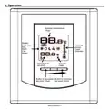
- Page 4: Operation Ambient temperature Timer Modes: Frost free, Day, Night, Fan, Smart Heating power used indicator Temperature set point Security mode Button to decrease set point/timer Button to increase set point/timer
- Page 5: Ambient temperature can be displayed in degrees Celsius or Fahrenheit. The Night mode features a timer that automatically returns to the Day mode after a selectable time period. The standard factory adjustment of the timer is 8 hours. The figures displayed above the icon indicate the temperature set point. Set points can be adjusted by increments of 0.5°C or 1°F. The minimum set point is 3°C (37°F), and the maximum set point is 30°C (86°F). In Day mode, you can turn off the thermostat by lowering the set point below 3°C. The thermostat includes a Day mode and a Night mode, both having independently adjustable set points. The standard factory set point adjustment is 21°C for the Day mode, and 18°C for the Night mode. The current Day/Night mode selection is indicated on the display by the Sun or Moon icon.
- Page 6: If needed, adjust the timer by pressing down the right button to increase the value, or the left button to decrease it. The adjustment range is from 1 hour to 999 hours. The 24-hour cycle starts with the Night mode as soon as the Smart mode is activated. The Night mode timer will be automatically reinitialized to the latest recorded value when switching from the Day mode to the Night mode. The Smart mode allows you to define two periods in a single day with different set points. If needed, adjust the timer by pressing down the right button to increase the value, or the left button to decrease it. The Night mode timer adjustment range is from 1 hour to 23 hours in the Smart mode. If you set the timer to any value exceeding 23 hours, it will be impossible to activate the Smart mode. Once activated, the Smart mode allows an automatic return to the Night mode after 24 hours. To quickly scroll through timer values, press and hold down the button. Activate the Smart mode by simultaneously pressing down the two buttons for at least 3 seconds.
- Page 7: If the Smart mode was already activated, the same procedure should be used to deactivate it. When the thermostat is used to control a heating system equipped with a fan, the Fan mode must be activated. The Fan mode is by default deactivated at the factory. It is always possible to manually change the Day/Night mode during a 24-hour cycle. A manual return to the Night mode will re-initialize the Night mode timer to the latest value recorded. The Snowflake icon is displayed when the temperature set point is between 3°C (37°F) and 5°C (41°F). The thermostat can display the ambient temperature and the set point in degrees Celsius or Fahrenheit. It is possible to impose a maximum temperature set point by activating the Security mode. To unlock the set point, you must cut off the power supply of the thermostat for security purposes. Press down the right button to switch from degrees Celsius to degrees Fahrenheit, and conversely.
- Page 8: Heating power indicator shows the level of power used to maintain the temperature at the set point as a percentage indicated by the number of bars in the thermometer displayed. 0 bar indicates no heat, while 1 bar represents 1% to 25%, 2 bars represent 25% to 50%, 3 bars represent 50% to 75%, and 4 bars represent 75% to 100%. To deactivate the security mode, cut off the power supply of the thermostat at the electrical panel. After cutting off the power supply, wait at least 20 seconds before restoring it. If there is a power failure, the adjustments are automatically saved and recovered when power is restored. The thermostat will return to Day mode if Smart mode was previously deactivated. To unlock the thermostat, press down the two buttons for more than 10 seconds until the icon disappears. If the thermostat isn’t unlocked within 5 minutes after the restoration of power supply, the icon will stop blinking. It will be impossible to unlock the thermostat unless the power supply is cut off again.
- Page 9: Troubleshooting In normal operating conditions, the thermostat housing can reach nearly 40°C at maximum load. That is normal and will not affect the effective operation of the thermostat. The thermostat is hot. Check if the thermostat is properly connected. Refer to the installation section. Heating is always on. Check if the thermostat is properly connected. Check the power supply at the electrical panel. Check if the heating unit has a switch. The display does not come on. The thermal protection of the heating unit has opened due to overheating. The display turns off a few minutes and then turns on again. The display has low contrast when heating is on. The load is lower than the minimum load. The displayed ambient temperature is incorrect. Check the presence of an air stream or a heat source near the thermostat. The display indicates E1 or E2. Faulty thermal sensor. Contact customer service. Possibility of a bad contact. Check thermostat wirings.
- Page 10: Technical specifications Supply voltage: 120/208/240 VAC, 50/60 Hz This unit has a 3-year warranty. In order for the warranty to be valid, the unit must have been installed and used according to instructions. The warranty is limited to the factory repair or the replacement of the unit. Minimum electrical current with a resistive load: 1.2 A Maximum electrical current with a resistive load: 16.7 A Temperature display range: 0°C to 40°C (32°F to 99.5°F) Temperature set point range: 3°C to 30°C (37°F to 86°F) Storage temperature: -20°C to 50°C (-4°F to 120°F) Certification: cCSAus