Midea KJR-29B-BK-E Wireless Thermostat Instruction Manual
R410A DC Inverter V4 Plus 50Hz
MCAC-VTSM-2013-03
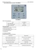
Touch- style key wired controller: KJR-29B/BK-E
ꢀ
KJR-29B/BK-E
Wired controller specifications
Model
KJR-10B/DB(T)-E
Power Supply Voltage
5.0V DC
-5°C~43°C
Ambient Temperature Range
Ambient Humidity Range
RH40%~RH90%
Performance Features
1. Operating mode: Cool, heat, dry, fan and auto.
2. Set the mode through buttons.
3. Indoor setting temperature range: 17°C ~30°C.
4. LCD (Liquid Crystal Display).
5. Touch-style key
2.3.1 Function summarize
KJR-29B is the touch-style key wired controller.
New function
Basic function
ON and OFF the air-conditioner
Auto-restart function
Air filter cleaning reminding function
Indoor unit address setting function
Remote control receiver function
Lock the wired controller
Time ON and Time OFF setting
Clock setting
26℃ operation shortcut setting and 26℃ operation lock
Setting the Operating mode, Temperature
Fan speed and Swing functions
Follow me
Control system
185
ꢀ
| General | Details |
|---|---|
| Name | Midea KJR-29B-BK-E Wireless Thermostat Instruction Manual |
| Make | Midea |
| Language | English |
| Filetype | PDF (Download) |
| File size | 0.33 MB |

Midea KJR-29B-BK-E Wireless Thermostat Instruction Manual Overview
Summary of Contents
- Page 1: R410A DC Inverter V4 Plus 50Hz Touch-style key wired controller: KJR-29B/BK-E Wired controller specifications Power supply voltage: 5.0V DC Ambient temperature range: -5°C to 43°C Ambient humidity range: RH40% to RH90% Operating modes: Cool, heat, dry, fan, and auto Indoor setting temperature range: 17°C to 30°C KJR-29B is the touch-style key wired controller Functions include ON/OFF control, auto-restart, air filter cleaning reminder, and time settings.
- Page 2: R410A DC Inverter V4 Plus 50Hz Wired controller appearance There is the signal receiver for wireless remote controller on the KJR-29B. You can use the wireless remote controller to control the air-conditioner through the wired remote controller when the system has been powered on. The wired controller will not receive the swing controlling instruction. Press the ON/OFF button to control the indoor unit on and off status. Press the mode button to set the operating mode. The operation mode will circle through AUTO, COOL, DRY, HEAT, and FAN. Under COOL, HEAT, and FAN modes, press the fan speed button to adjust the fan speed setting. Under AUTO and DRY modes, the fan speed is not adjustable and the default fan speed is auto.
- Page 3: Temperature setting allows adjustment between 17℃ and 30℃ under various modes, except FAN mode. Timer on and off settings can be adjusted with the timer/clock setting button, with a maximum of 24 hours. Clock setting involves long pressing the timer/clock button to adjust hours and minutes. The 26℃/OK button sets the operating temperature to 26℃ and can lock this setting. Wired controller locking prevents button responses and can be activated by pressing temperature adjusting buttons simultaneously. Air filter cleaning reminder activates after a pre-set running time, indicating the need for cleaning. The default reminder setting is 2500 hours, adjustable to other values. Swing function allows adjustment of air outlet direction and can activate auto-swing with a long press. The wired controller records total running time for maintenance reminders. Long pressing buttons can confirm settings and exit adjustment modes.
- Page 4: R410A DC Inverter V4 Plus 50Hz Follow Me function activates when the system is running in AUTO, COOL, or HEAT mode. Pressing the left button activates or cancels the Follow Me function. The wired controller displays room temperature from the local sensor and transmits it to the indoor unit every 3 minutes when the function is active. To enter address setting mode, press the Temp. UP and DOWN buttons simultaneously for more than 8 seconds. In address setting mode, users can query or set the indoor unit's address. Press the MODE button to display the corresponding indoor unit's address. Use the UP and DOWN buttons to choose an address and press the FAN button to set it. After setting, the new address will be displayed for a few seconds before returning to normal mode. In address setting mode, the wired controller does not respond to commands from the remote controller. Preparation before installation requires specific components and tools.
- Page 5: Prepare for the following at installation site. Dimensions: 120*120*20mm Wiring principle sketch: 4-Core Shield Cable, the length is decided by installation. Indoor Unit Switch Board Indoor Unit Control system
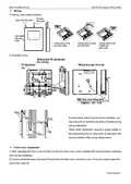
- Page 6: R410A DC Inverter V4 Plus 50Hz Connect two terminals of embedded 4-core shielding wire with the switching wires of wired remote controller and signal receiving board. Make sure the sequence of 4 terminals (A/B/C/D) corresponds to the wire sequence of signal switching wires (A/B/C/D). If embedded 4-core shielding wire cannot go through the wired controller, use signal switching for connection and ensure the wires are reliable and firm. The tightening torque range of the screw is 0.8~1.2N.m (8~12 kgf.cm). Use a straight head screwdriver to insert into the buckling position in the bottom of a wired controller to take down the back cover. Pay attention to spinning direction when removing the back cover to avoid damage.
- Page 7: R410A DC Inverter V4 Plus 50Hz Use three GB950-86 M4X20 screws to directly install the back cover on the wall. Use two M4X25 GB823-88 screws to install the back cover on the 86 electrician box. Adjust the length of two plastic screw bars in the accessory to be the standard length from the electrical box screw bar to the wall. Make sure when installing the screw bar to the electrical box screw bar, it is flat against the wall. Use cross head screws to fix the wired controller bottom cover in the electric control box through the screw bar. Ensure the wired controller bottom cover is on the same level after installation. Over fastening the screw will lead to deformation of the back cover.
- Page 8: Wiring instructions include three outlet positions: top side, upper left, and left middle side. Shielded wiring is recommended for installation. Use putty to seal the connectors of wires to prevent water from entering the wired controller. Reserve a certain length of the connecting wire for maintenance convenience. Adjust and buckle the front cover carefully to avoid clamping the communication switching wire. Ensure the back cover is correctly installed and firmly buckled to prevent the front cover from dropping off. The document includes information about the control system.
- Page 9: Wired controller initial parameters setting involves changing related functions through adjusting initial parameters. The wired controller initial parameter includes two codes: XY, where X indicates function class and Y indicates detailed configuration. To enter the parameter setting state, simultaneously press Mode and Fan button for 5 seconds. Adjust the second code value using the temperature setting button UP and DOWN after setting the first code X. Press the 26/OK button to switch to the next first code value after setting the second code. Exit the parameters setting when the first code value is 6 by pressing the 26/OK button again. The parameters setting function is only necessary when adjusting default functions' setting states. Table 1 outlines various functions and their corresponding codes for configuration. Functions include cool-only/cool-heat selection, communication address setting, auto-restart, and air filter cleaning reminding function. The control system is referenced with a specific code number.