Home > VENSTAR > VENSTAR Fan Coil Thermostat T2100 / T2150 User Guide

VENSTAR Fan Coil Thermostat T2100 / T2150 User Guide

FAN COIL THERMOSTAT  
models T2100 / T2150  
with  
Wi-Fi  
and local  
API  
Quick start  
and setup guide  
GeneralDetails
NameVENSTAR Fan Coil Thermostat T2100 / T2150 User Guide
MakeVENSTAR
LanguageEnglish
FiletypePDF (Download)
File size0.34 MB
Download PDF
1 Star2 Stars3 Stars4 Stars5 Stars (1 votes, average: 5.00 out of 5)
Loading...

VENSTAR Fan Coil Thermostat T2100 / T2150 User Guide
Get the free PDF manual for the VENSTAR Fan Coil Thermostat T2100 / T2150 User Guide and access setup steps, usage instructions, and troubleshooting tips. 👉 View online or download now to keep your thermostat running smoothly!

VENSTAR Fan Coil Thermostat T2100 / T2150 User Guide Overview

Summary of Contents

  • Page 1: Fan coil thermostat models T2100 / T2150 with Wi-Fi and local API. Quick start and setup guide.
  • Page 2: Thank you for purchasing your new Venstar Fan Coil thermostat. This guide is intended to help you install and set up the basic features of your thermostat. For a full owner’s manual and installation guide, visit Venstar.com.
  • Page 3: Your Venstar EXPLORER Mini fan coil thermostat is designed to work with 24V fancoils, both 2 pipe or 4 pipe. For 2 pipe units with automatic changeover between heating and cooling based on water supply, you will need to obtain a H2O changeover switch, ACC-SENFC. The thermostat controls 3 speed fans and can control to a remote temperature sensor. Necessary tools include a level, pliers, smart phone, drill or hammer, WiFi network & password, screw driver, and pencil.
  • Page 4: Power off current system All power must be disconnected before any installation or service is attempted. More than one power source may be supplied to a unit. Power to remote mounted control devices may not be supplied through the unit. To confirm power is off, adjust the temperature on your current thermostat. Warning: Failure to follow this step can result in personal injury and/or death from shock and electrocution. Remove faceplate Remove the faceplate of current system. Most faceplates snap-off or feature small screws that will need to be removed. Warning: If you see large thick electrical wires, wire nuts, or if your system is labeled 120V, 240V, or 277V do not proceed. This thermostat is not compatible with these systems. Warning: Failure to follow this step can result in personal injury and/or death from shock and electrocution.
  • Page 5: Label and disconnect wires. Before disconnecting any wires, take a photo of your current wire configuration with your mobile device. One by one, apply a label designated to each wire you disconnect from your current thermostat. Wire from the old thermostat terminal marked G1, GL corresponds to low fan speed. Wire from the old thermostat terminal marked G2, GM corresponds to middle fan speed. Wire from the old thermostat terminal marked G3, GH corresponds to high fan speed. Wire from the old thermostat terminal marked Y, Y1 is for the chilled water valve or hot/chilled water valve. W, W1 is for the hot water valve or strip heat. H/C, WATER is for the 2 pipe water temperature sensor. CK1 is a dry contact for condensate overflow, occupancy sensor, or door switch.
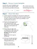
  • Page 6: Remove current backplate by unscrewing it from the wall and be careful not to let the wires fall into the wall. If needed, wrap the wires around a pencil or pen to keep them from falling inside the wall. Gently separate the display from the base by pulling from one side, then the other until the two pieces unsnap. Position the base against your wall and determine if wall anchors from the current thermostat align with screw locations of the new base. If the base does not align with existing anchor holes, mark new screw locations with a pencil. For drywall, drill a 3/16 hole for the anchor. For plaster, drill a 7/32” hole for the anchor. Pull wires through the opening in the base and secure to the wall using provided screws. Use a level to ensure the thermostat is properly aligned before marking screw locations.
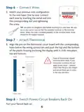
  • Page 7: Connect wires by matching the previous wire configuration to the new base. Insert the metal end into the corresponding slot and tighten the screw. Use pliers to straighten the wire before inserting it into the new base. Cut any excess wire so that the insulation extends to the terminal block. Ensure no copper is exposed when the wire is installed properly. Attach the thermostat by aligning the pins on the thermostat circuit board with the corresponding holes below the wiring connectors. Push the top and bottom of the plastic housing until it clicks into place. If there is resistance, remove and check that the pins are straight and ensure there are no wires in the way. Switch power or circuit breakers back on to turn the fancoil back on.
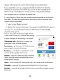
  • Page 8: Set up Wi-Fi connection At minimum, the first 3 tasks below must be completed to access your thermostat remotely from a browser. The 4th step is optional and only is needed to access your thermostat(s) from a mobile device. These steps are: Successful connection to a local Wi-Fi Access Point with internet access. Confirm receipt of a Skyport generated verification email. A 6-digit code obtained from the thermostat is successfully entered into a Skyport account. Successfully download and install the Venstar Skyport app on your mobile device(s). Your thermostat operates on the 2.4 GHz, Wi-Fi b/g/n band. Table of button presses to enter menus.
  • Page 9: Quick start - Connect to Wi-Fi The Explorer thermostats are joined to a Wi-Fi network with the help of the Venstar Configurator App. This app may be downloaded from your mobile device’s app store. Once the thermostat is installed and powered, the Configurator App will facilitate connection to the access point in 6 steps. Go to the settings of the mobile device. Press and hold the FAN button for 5 seconds. When “Wireless Setup” appears on the display, release the FAN button. Then press the COOLER button on the thermostat to configure Wi-Fi. Select “Setup Wi-Fi” on the Configurator App. Enter the password: 123456789 when prompted.
  • Page 10: Quick Start - Connect to Wi-Fi Select the access point of your building or home to join. Enter the network password and select “Done.” Then press “Continue” in the lower right corner to complete setup. When completed, the full Wi-Fi symbol will appear on the display. Scan with mobile device for additional information.
  • Page 11: Quick Start - Connect to Skyport To create a Skyport account, a thermostat must be joined to the account. If the thermostat is connected to the local Wi-Fi Access Point, you may create an account and join the thermostat by following the steps. Open your browser to: http://venstar.skyportcloud.com. Select “Create account now.” Follow on-screen instructions to create an account and add a thermostat. If the thermostat is connected but not yet joined to an existing Skyport account, log in to your Skyport account. Select the “Location” you want to add a thermostat into. Select the “Thermostat tab.” Select “+ Add Thermostat.” A screen will pop up asking for a six-digit code. Press and hold the fan button on the thermostat for 5 seconds to get the six-digit code.
  • Page 12: Skyport will maintain the correct time and day on your thermostat. You can set up a program/schedule to maintain the desired temperature at various times of the day manually or through the Skyport website. The complete manual is available at venstar.com. It is easier to set up the time period program/schedule on the Skyport Web App. To make adjustments to your thermostat from Skyport, log in to your Skyport account. Choose the location where your thermostat is installed. You can control basic functions of the thermostat like mode, setpoints, or fan speed. You can customize the settings by pressing on the upper right section of the panel. Thermostat info allows you to name the thermostat and view software revision. Permissions enable you to grant access to other users.
  • Page 13: Troubleshooting guide to diagnose common problems. Display won’t turn on due to lack of proper power. Make sure that the fancoil unit is powered and check for 24 VAC between R and C at backplate. Cooling won’t turn on if the cool setpoint is set too high. Lower the cool setpoint, minimum setpoint limit, or reduce deadband. Heating won’t turn on if the heat setpoint is set too low. Raise the heat setpoint, maximum setpoint limit, or reduce deadband. Two pipe auto changeover fancoil shows heat with chilled water or cool with hot water due to an incorrect water changeover switch. Contact Venstar for proper changeover switch specifications. 2 pipe water valve won’t open in heat or cool if it is not wired to Y1 terminal. Check wiring for the 2 pipe water valve.
  • Page 14: Troubleshooting The thermostat won’t connect to the access point. Possible causes include wrong password, access point offline, or no internet connection on access point. Solutions involve entering the correct password, bringing the access point online, or restoring internet. Can’t connect to Skyport may be due to firewall restrictions or factory default thermostat. To resolve, check firewall settings or remove the thermostat from the Skyport account. Can’t get a 6 digit pairing code could be because the thermostat is already in an account or due to no internet connection. Restoring internet or checking firewall settings may help in these cases.
  • Page 15: Warranty This product is warranted to be free from defects in material and workmanship for one year from the date of original installation. A new or remanufactured part will be provided without charge for the part itself if the product does not meet this warranty. This warranty does not include labor or other costs incurred for diagnosing, repairing, or handling defective parts. The warranty applies only to products in their original installation location and becomes void upon reinstallation. All implied warranties are limited in duration to the period for which the limited warranty is given. The expressed warranties made in this warranty are exclusive and may not be altered by any distributor or dealer. All work under the terms of this warranty shall be performed during normal working hours. Replacement parts assume the remaining time period of this warranty. The manufacturer will not be responsible for normal maintenance, damage due to faulty installation, or failure to start due to electrical issues. This warranty gives you specific legal rights, which may vary from state to state.