Danfoss RET230 HCW-1 Electronic Heat Cool Thermostat User Manual
RET 230 HCW-1
Electronic Heat / Cool thermostat with
auto-changeover based on water temperature
Installation Instructions
User Instructions
Installatie handleiding
Instructiesevoor Gebruik
NL
GB
F
Instructions d’installation
Instructions d’utilisateur
Ïäçãßåò åãêáôÜóôáóçò
Ïäçãßåò ÷ñÞóçò
GR
PL
LT
Anweisungen für Installati
Benutzeranweisen
Instrukcja instalacji
D
Instrukcja Użytkownika
Instrucciones de instalación
Instrucciones del usuario
Montavimo instrukcijos
Informacija Vartotojui
ES
DK
Instruktions vejledning
Brugervejleding
Istruzioni per l’uso
Istruzioni per l’utente
I
| General | Details |
|---|---|
| Name | Danfoss RET230 HCW-1 Electronic Heat Cool Thermostat User Manual |
| Make | Danfoss |
| Language | English |
| Filetype | PDF (Download) |
| File size | 0.77 MB |

Danfoss RET-MD Electronic Intelligent Dial Setting Thermostat Installation Guide
Danfoss VICUQ24M Icon Programmable II Room Thermostat Installation Guide

Danfoss MBC 8000, MBC 8100 Heavy Duty Thermostat Installation Guide

Danfoss UT 72-UT 73 Universal Thermostat Installation Guide

Danfoss ECtemp 530 Electronic Thermostat Installation Guide

Danfoss 014G0251 Eco Radiator Thermostat User Guide

Danfoss RET230P Electronic Thermostat Instruction Manual

Danfoss 014G0013 Z Wave Radiator Thermostat Installation Guide

Danfoss TP7000 Range Electronic 7 Day Programmable Room Thermostat Installation Guide

Danfoss RET1000 Series Electronic Thermostat User Guide

Danfoss RET230 HCW-1 Electronic Heat Cool Thermostat User Manual Overview
Summary of Contents
- Page 1: Electronic heat/cool thermostat with auto-changeover based on water temperature. Installation instructions. User instructions. Instructions d’installation. Instructions d’utilisateur. Instrukcja instalacji. Instrukcja użytkownika. Instrucciones de instalación. Instrucciones del usuario. Montavimo instrukcijos.
- Page 2: Installation instructions User instructions Instructions d’installation Instructions d’utilisateur Anweisungen für Installation Benutzeranweisungen Instrucciones de instalación Instrucciones del usuario Instruktions vejledning Brugervejledning
- Page 3: Installation instructions should only be performed by a qualified electrician or heating installer. The installation must comply with local building regulations and wiring regulations. Thermostat features include a temperature range of 5-30°C. Water changeover temperature settings are >30°C for cool to heat and <16°C for heat to cool. The thermostat has an off/auto & fan on selector. Power supply requirements are 30 Vac ± 15%, 50/60Hz. Relay outputs for heat/cool & fan are 1 x SPS, 3(1)A, 10-30 Vac, Type 1B. Dimensions of the thermostat are 110 mm wide x 90 mm high x 40 mm deep. The design standard is EN60730-1-9. Temperature accuracy is ±1°C.
- Page 4: Product overview The thermostat is designed for use in systems equipped with fan coils served by a pipe central changeover system. The thermostat controls the operation of a motorized valve which opens when heat or cooling is required. The changeover from heating to cooling is achieved automatically by measuring the temperature of the flow pipe. If the flow temperature exceeds 30°C, the thermostat operates as a heating thermostat; if it is less than 16°C, it operates as a cooling thermostat. It is essential that the circuit in which the pipe sensor is located is not closed off and that water circulates past the sensor at all times. This may require the fitting of a bypass valve between system flow and return at the end of each circuit. Installation First remove the wallplate from the back of the unit. Ensure that there is a minimum of 50mm above the unit and 100mm below the unit in order to mount the plug-in module.
- Page 5: Fix the sensor at a height of approximately 1.5m from the floor, away from draughts or heat sources. Fix the pipe sensor to the flow pipe using the clamping band supplied. It is essential that the circuit in which the pipe sensor is located is not closed off and that water circulates past the sensor at all times when the system is in operation. This may require the fitting of a bypass valve between system flow and return to ensure circulation past the sensor.
- Page 6: Wiring 2-pipe fan coil application Electronics Fan If HEAT/COOL/FAN outputs are ꢀ30V, link terminals L-COM
- Page 7: Commissioning Prior to re-fitting the thermostat to the wallplate, the DIL switches on the rear of the unit must be set to the desired setting. DIL switch options, shown in factory set position (all switches in On position).
- Page 8: DIL switch descriptions Switch 4: If set to On/Off, both heating and cooling operates in on/off mode. If set to Chrono, both heating and cooling operates in chrono-proportional mode. Switch 3: Active only if switch 4 is set to Chrono. This switch determines the number of cycles per hour that the thermostat will impose on the system, the options are three 20 minute cycles or six 10 minute cycles. Switch 2: Allows Celsius or Fahrenheit temperature scaling to be selected. Switch 1: Not used in this model.
- Page 9: Mounting thermostat to the wallplate involves aligning the tabs on the top of the thermostat with the apertures in the wallplate and hinging the thermostat down. To lock or limit the setting range, turn the setting dial to 3 and remove the knob. Position the locking springs on the rear of the dial to the desired position and re-mount the knob, ensuring that number 3 on the dial aligns with the reference mark on the case.
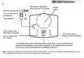
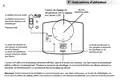
- Page 10: User instructions for temperature setting dial are provided. The LCD display shows the actual room temperature unless the knob is moved, which causes a flashing set temperature to be displayed momentarily. During heating demand, a flame symbol is lit, and during cooling demand, a snowflake symbol is lit. The reset button is located beneath the setting dial for microprocessor resets. A non-metallic point, such as a matchstick, should be used to depress the recessed reset button. The fan can run continuously or with heat or cool demand. The thermostat is off when the LED is not lit. The LED is lit green when the thermostat is powered and during heating or cooling demand. The LED is lit orange when the fan is running.
- Page 11: Instructions d'installation Ce produit doit être installé exclusivement par un électricien qualifié ou un installateur de chauffage compétent. Il doit être conforme à la version en vigueur des réglementations de câblage IEEE. Thermostat features Plage de températures, chauffage 5-30°C. Temp de commutation - Refroidissement à Chauffage et Chauffage à Refroidissement. Sélecteur arrêt/automatique thermostat & marche ventilateur. Alimentation 30 Vac ± 15%, 50/60Hz. Sorties relais, chauffage/refroidissement & ventilateur. Dimensions (mm) 110 largeur, 90 hauteur, 40 épaisseur. Normes de fabrication, tension de choc nominale. Précision de la température ±1°C.
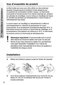
- Page 12: Vue d’ensemble du produit Le thermostat est conçu pour être utilisé sur des systèmes équipés d’évaporateurs à ventilation forcée. Le thermostat commande le fonctionnement d’un robinet motorisé. La commutation du chauffage au refroidissement s’effectue automatiquement en mesurant la température du tuyau d’écoulement. Si la température d’écoulement dépasse 30°C, le thermostat fonctionne comme un thermostat de chauffage. Si la température d’écoulement est inférieure à 16°C, le thermostat fonctionne comme un thermostat de refroidissement. Il est primordial que le circuit dans lequel se trouve le capteur de tuyau ne soit pas fermé. Ceci peut nécessiter l’installation d’un robinet de dérivation entre l’écoulement et le retour du système. Installation Retirez tout d’abord la plaque murale de l’arrière de l’appareil. Vous devez disposer d’espacements d’au moins 50 mm au-dessus et 100 mm en-dessous afin de pouvoir monter le module enfichable.
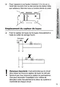
- Page 13: Fixez l’appareil à une hauteur d’environ 1,5 m du sol, à l’écart des courants d’air ou des sources de chaleur telles que radiateurs, flammes nues ou lumière directe du soleil. Fixer le capteur de tuyau sur le tuyau d’écoulement à l’aide du collier de serrage fourni. Il est primordial que le circuit dans lequel se trouve le capteur de tuyau ne soit pas fermé et que l’eau traverse le capteur en permanence. Ceci peut nécessiter l’installation d’un robinet de dérivation entre l’écoulement et le retour du système à l’extrémité de chaque circuit.
- Page 14: Câblage Application évaporateur à ventilation forcée 2 tuyaux Electronique Ventilateur 1 vitesse Capteur de tuyau PS1 230 VCA 3A Fixe Remarque: Si les sorties CHAUFFAGE/REFROIDISSEMENT/VENTILATEUR sont de 30V, relier les bornes L – COM
- Page 15: Instructions Avant de remonter le thermostat sur le support mural, les interrupteurs à DRC à l’arrière de l’appareil doivent être placés dans les positions de réglage désirées. Options interrupteurs à DRC, illustrés en position réglés en usine (tous les interrupteurs en position Marche).
- Page 16: Descriptions des interrupteurs à DRC Interrupteur 4: En position Marche/Arrêt, la phase de chauffage et la phase de refroidissement fonctionnent en mode marche/arrêt. En position Chrono, la phase de chauffage et la phase de refroidissement fonctionnent en mode chrono-proportionnel. Interrupteur 3: Activé uniquement si l’interrupteur 4 est en position Chrono. Cet interrupteur détermine le nombre de cycles par heure que le thermostat imposera au système, les options sont trois cycles de 40 minutes ou six cycles de 10 minutes. Interrupteur 2: Permet de sélectionner les échelles de température Celsius ou Fahrenheit. Interrupteur 1: Non utilisé sur ce modèle.
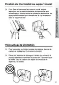
- Page 17: Fixation du thermostat au support mural Pour fixer le thermostat au support mural, aligner les ergots sur la partie supérieure du thermostat aux ouvertures du support mural et rabattre le thermostat, en appuyant fermement pour enclencher le clip de fixation dans le support mural. Verrouillage & Limitation Pour verrouiller ou limiter la plage de réglage, tourner le cadran de réglage sur 3 et retirer le bouton. Placer les ressorts de blocage à l’arrière du cadran à la position désirée et remonter le bouton en s’assurant que le chiffre 3 sur le cadran soit aligné à la marque de repère sur le boîtier.
- Page 18: Instructions d’utilisateur Le ventilateur tourne en continu. Le ventilateur tourne avec la demande de chauffage ou de refroidissement. La diode est allumée en vert lorsque le thermostat est sous tension. La diode est allumée en orange lorsque le ventilateur tourne. L’écran LCD affiche la température ambiante effective. Un symbole de flamme est allumé pendant la demande de chauffage. Un symbole de flocon de neige est allumé pendant la demande de refroidissement. Un bouton de réinitialisation se trouve sous le cadran de réglage. Utiliser une pointe non métallique pour enfoncer le bouton encastré.
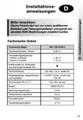
- Page 19: Installationsanweisungen Dieses Produkt darf nur von einem qualifizierten Elektriker oder Heizungsinstallateur und gemäß den aktuellen IEEE-Bestimmungen installiert werden. Technische Daten Temperaturbereich, Heizen: 5-30 °C Umschaltungstemperatur: > 30 °C (Kühlen zu Heizen), < 16 °C (Heizen zu Kühlen) Wahlschalter für Thermostat: Aus/Automatik/Ventilator Ein Stromversorgung: 30 Vac ± 15 %, 50/60 Hz Relaisausgänge, Heizen/Kühlen und Ventilator: 3(1)A, 10-30 Vac, Typ 1B Abmessungen (B x H x T): 110 x 90 x 40 mm Temperaturgenauigkeit: ±1 °C
- Page 20: Produktübersicht Der Thermostat ist für den Einsatz in Heiz- und Kühlsystemen im ꢀ-Rohr-System mit Ventilator-Luftkühlern gedacht. Die Umschaltung von Heizen auf Kühlen erfolgt über ein zentrales Umschaltsystem. Der Thermostat regelt den Betrieb eines elektrischen Ventils, das während der Heizperiode den Wärmebedarf und während der Kühlperiode den Kühlbedarf regelt. Der Übergang von Heizen auf Kühlen erfolgt automatisch durch Temperaturmessung am Vorlaufrohr. Übersteigt die Temperatur 30 °C, arbeitet der Thermostat als Heizthermostat, bei Temperaturen unter 16 °C als Kühlthermostat. Wichtiger Hinweis: Der Kreislauf, in dem sich der Anlegefühler befindet, darf nicht gesperrt sein und Wasser muss jederzeit am Fühler vorbeifließen. Hierzu kann u. U. der Einbau eines Bypass-Ventils zwischen Systemfluss und Rücklauf am Ende jedes Heiz-/Kühlkreises erforderlich sein. Installation Entfernen Sie zuerst die Wandplatte auf der Geräterückseite. Um das Einsteckmodul zu befestigen, sind 30 mm nach oben und 100 mm nach unten freizuhalten.
- Page 21: Befestigen Sie den Thermostaten in einer Höhe von 1,5 m über dem Boden, frei von Luftzug oder Wärmequellen. Bringen Sie den Anlegefühler mit Hilfe des mitgelieferten Spannbands am Vorlaufrohr an. Der Kreislauf, in dem sich der Anlegefühler befindet, darf nicht gesperrt sein und Wasser muss jederzeit am Fühler vorbeifließen. Der Einbau eines Bypass-Ventils zwischen Systemfluss und Rücklauf am Ende jedes Heiz-/Kühlkreises kann erforderlich sein.
- Page 22: Verdrahtung Ventilator-Luftkühlung bei 2-Rohr-Systemen Hinweis: Wenn die Ausgänge Heizen / Kühlen / Ventilator mit 30 V versorgt werden, wird die Klemme (L) mit der Klemme (COM) verbunden (gebrückt).
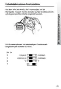
- Page 23: Inbetriebnahme-Instruktion Vor dem erneuten Anbau des Thermostats auf die Wandplatte müssen die DIL-Schalter auf der Geräterückseite auf die gewünschten Werte eingestellt werden. DIL-Schalteroptionen, mit werkseitigen Einstellungen dargestellt (alle Schalter auf Ein).
- Page 24: DIL-Schalterbeschreibungen Schalter 4: Bei Einstellung auf Ein/Aus erfolgt sowohl der Heiz- als auch der Kühlvorgang im Ein/Aus-Modus. Bei Einstellung auf Chrono erfolgt sowohl der Heiz- als auch der Kühlvorgang im zeitproportionalen Modus. Schalter 3: Nur dann aktiv, wenn Schalter 4 auf Chrono gestellt ist. Dieser Schalter bestimmt die Anzahl der Zyklen pro Stunde, die der Thermostat dem System beibringt. Es stehen die Optionen 3 Zyklen (alle 20 Minuten) oder 6 Zyklen (alle 10 Minuten) zur Auswahl. Schalter 2: Ermöglicht wahlweise Temperaturangabe in Celsius oder Fahrenheit. Schalter 1: In diesem Modell nicht verwendet.
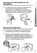
- Page 25: Anbringen des Thermostats an der Wandplatte Zur Anbringung des Thermostats auf die Wandplatte sind die Nasen auf der Thermostatoberseite mit den Aussparungen in der Wandplatte in Übereinstimmung zu bringen und nach unten einzuhängen. Durch Andrücken die Befestigungsklemme in der Wandplatte zu verankern. Blockieren & Begrenzen Zum Blockieren oder Begrenzen des Einstellbereichs die Einstellscheibe auf 3 einstellen und Stellknopf entfernen. Positionieren Sie die Blockierfedern auf der Rückseite der Einstellscheibe auf die gewünschte Position. Bringen Sie den Stellknopf wieder an, wobei sicherzustellen ist, dass Stellung Nummer 3 auf der Einstellscheibe mit der Bezugsmarke auf dem Gehäuse in Übereinstimmung gebracht wird.
- Page 26: D - Benutzeranweisung Temperatureinstellscheibe, lesen Sie die Einstellung von der LCD-Anzeige ab. Ventilator läuft ohne Unterbrechung. Automatik: Ventilator läuft mit Wärme- oder Kühlbedarf. Grüne LED-Lampe leuchtet bei Thermostatbetrieb. Grüne LED-Lampe leuchtet während Heiz- oder Kühlbedarf. Orange LED-Lampe leuchtet bei laufendem Ventilator. Das LCD-Display zeigt die aktuelle Raumtemperatur an. Während des Heizbedarfs leuchtet ein Flammensymbol, während des Kühlbedarfs ein Schneeflockensymbol auf. Hinweis: Sollte die Rücksetzung des Mikroprozessors erforderlich sein, befindet sich ein Resetknopf unterhalb der Einstellscheibe. Verwenden Sie einen nichtmetallischen spitzen Gegenstand, um den Resetknopf zu drücken.
- Page 27: Instrucciones de instalación Este producto deberá ser instalado solamente por un electricista cualificado o por un instalador de calefacción competente. Deberá instalarse de acuerdo con la edición vigente de las normas de cableado de la IEEE. Rango de temperaturas, calefacción 5-30°C. Cambio de temp. - Refrig. a Calef. > 30°C. Cambio de temp. - Calef. a Refrig < 16°C. Selector de termostato desconectado/auto y ventilador conectado. Alimentación 30 Vac ± 15%, 50/60Hz. Dimensiones (mm) 110 An x 90 Al x 40 Pr. Precisión de temperatura ±1°C. Norma de fabricación EN60730-1-9.
- Page 28: Generalidades sobre el producto El termostato ha sido diseñado para ser utilizado en sistemas provistos de fan-coil servidos por un sistema central de cambio de tuberías. El termostato controla el funcionamiento de una válvula motorizada que, durante los períodos de calefacción, se abre cuando se requiere calor y que, durante los períodos de refrigeración, se abre cuando se requiere refrigeración. Este cambio de calefacción a refrigeración se consigue automáticamente midiendo la temperatura de la tubería de impulsión. Si la temperatura de impulsión excede de 30°C, el termostato funciona como uno de calefacción, si la temperatura de impulsión es inferior a 16°C, el termostato funciona como uno de refrigeración. Nota importante: Es esencial que el circuito en que se encuentra el sensor de tubería no esté desconectado y que el agua circule continuamente después del sensor. Instalación En primer lugar, quitar la placa mural de la parte trasera de la unidad. Debe haber un espacio libre de al menos 50mm arriba y de 100mm abajo con el fin de montar el módulo enchufable.
- Page 29: Montarlo a una altura de aproximadamente 1,5 m desde el suelo, lejos de corrientes de aire o de fuentes de calor. Fije el sensor de tubería a la tubería de impulsión utilizando la banda de unión que se suministra. Es esencial que el circuito en que se encuentra el sensor de tubería no esté desconectado y que el agua circule continuamente después del sensor. Esto puede requerir la instalación de una válvula de derivación entre el flujo y el retorno del sistema al final de cada circuito.
- Page 30: Cableado Aplicación como fan-coil de 2 tuberías Sistema electrónico Ventilador de 1 velocidad Sensor de tubería PS1 Nota: Si las salidas HEAT/COOL/FAN son a 30V, conecte entre sí los terminales L – COM
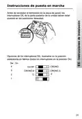
- Page 31: Instrucciones de puesta en marcha Antes de reinstalar el termostato en la placa de pared, los interruptores DIL de la parte posterior de la unidad deben estar puestos en las posiciones deseadas. Opciones de los interruptores DIL, ilustrados en la posición establecida en fábrica.
- Page 32: Descripción de los interruptores DIL Interruptor 4: Si se pone en On/Off, funcionan la calefacción y refrigeración en el modo On/Off. Si se pone en Crono, funcionan la calefacción y refrigeración en el modo crono-proporcional. Interruptor 3: Solo se activa si el interruptor 4 está puesto en Crono. Este interruptor determina el número de ciclos por hora que el termostato hará trabajar al sistema; las opciones son tres ciclos de 40 minutos o seis ciclos de 10 minutos. Interruptor 2: Permite seleccionar la escala de temperatura Celsius o Fahrenheit. Interruptor 1: No se usa en este modelo.
- Page 33: Montaje del termostato en la placa de pared Para montar el termostato en la placa de pared, alinee las orejetas de la parte superior del termostato con las aberturas de la placa de pared y embisagre el termostato presionando firmemente hacia abajo para enganchar la presilla de seguridad en la placa de pared. Bloquear y Limitar Para bloquear o limitar el margen de ajuste, gire el cuadrante de ajuste a 3 y saque el botón. Coloque los resortes de bloqueo de la parte posterior del cuadrante en la posición deseada y vuelva a montar el botón cerciorándose de que el número 3 del cuadrante queda alineado con la marca de referencia de la caja.
- Page 34: Instrucciones de usuario Cuadrante de ajuste de temperatura; lea en el display LCD. El ventilador funciona continuamente. El ventilador funciona bajo demanda de calor o frío. Termostato desconectado. LED iluminado en verde cuando está activado el termostato. LED iluminado en naranja cuando está en funcionamiento el ventilador. El display LCD muestra la temperatura ambiente real a menos que se haya movido el botón. Durante la demanda de calefacción, se ilumina el símbolo de una llama. Durante la demanda de refrigeración, se ilumina el símbolo de un copo de nieve. Si fuera necesario reponer el microprocesador, se utilizará el botón de reposición situado bajo el cuadrante de ajuste.
- Page 35: Bemærk: Dette produkt må kun installeres af en uddannet elektriker eller kompetent varmeinstallatør, og installation skal ske i henhold til de gældende IEEE-standarder for trådføring. Temperaturområde, varme 5-30°C Omkoblingstemperatur - Kulde til varme > 30°C Omkoblingstemperatur - Varme til kulde < 16°C Batterier 30 Vac ± 15%, 50/60Hz Relæydelse, varme/kulde og ventilator 1 x SPS, 3(1)A, 10-30 Vac, Type 1B Mål (mm) 110 bred, 90 høj og 40 dyb Konstruktionsnorm EN60730-1-9 Nominel Impuls Spænding 0.5Kv Temperaturnøjagtighed ±1°C
- Page 36: Produktoversigt Termostaten er udviklet til brug i systemer med ventilationskonvektorer. Termostaten styrer en motoriseret ventil, som åbnes ved behov for varme eller kulde. Omskiftningen fra varme til kulde opnås automatisk ved måling af temperaturen i fremløbsrøret. Hvis fremløbstemperaturen overstiger 30°C, fungerer termostaten som opvarmningstermostat. Hvis fremløbstemperaturen er lavere end 16°C, fungerer termostaten som afkølingstermostat. Det er vigtigt, at kredsløbet med rørsensoren ikke er lukket, og at der cirkulerer vand forbi sensoren. Det kan være nødvendigt at montere en bypass ventil mellem fremløb og retur. Fjern først vægpladen bag på enheden. Der skal være en afstand på mindst 50 mm over vægpladen og 100 mm under vægpladen for montering af indstiksmodulet.
- Page 37: Monter den i en højde på ca. 1,5 m fra gulvet væk fra lufttræks- eller varmekilder såsom radiatorer, åben ild eller direkte sollys. Monter rørsensoren på gennemstrømningsrøret ved hjælp af den medfølgende fastspændingsrem. Det er vigtigt, at det kredsløb, som rørsensoren er placeret i, ikke er lukket af, og at der hele tiden cirkulerer vand forbi sensoren. Det kan gøre det nødvendigt at montere en bypass ventil mellem fremløb og retur i enden af hvert kredsløb.
- Page 38: Ledningsføring Ventilationskonvektor med 2 rør Elektronik Ventilator med 1 hastigheder PS1-rørsensor 230 VAC fast 3A Hvis VARME/KULDE/VENTILATOR-effekten er ꢀ30 V, skal klemmerne L – COM forbindes
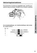
- Page 39: Aktiveringsinstruktioner Før termostaten monteres på vægpladen igen, skal DIL-kontakterne bag på enheden indstilles til den ønskede indstilling. DIL-kontaktindstillinger, vist i fabriksindstillingen (alle kontakter i tændt position)
- Page 40: DIL-kontaktbeskrivelser Kontakt 4: Hvis den er indstillet til On/Off, kører både varme- og kuldefunktionen i on/off-tilstand. Hvis den er indstillet til Chrono, kører både varme- og kuldefunktionen i tidsmæssigt proportional tilstand. Kontakt 3: Kun aktiv, hvis kontakt 4 er indstillet til Chrono. Denne kontakt bestemmer antallet af kredsløb pr. time, som termostaten pålægger systemet. Valgmulighederne er tre kredsløb á 10 minutter eller seks kredsløb á 10 minutter. Kontakt 2: Giver mulighed for at vælge mellem Celsius eller Fahrenheit. Kontakt 1: Bruges ikke i denne model.
- Page 41: Montering af termostaten på vægpladen For at montere termostaten på vægpladen, skal tapperne oven på termostaten rettes ind med åbningerne i vægpladen, og termostaten skal hængsles fast. Dette gøres ved at trykke godt til for at fæstne holderen til vægpladen. Låsning og begrænsning For at låse eller begrænse indstillingsområdet skal indstillingshjulet drejes til 3 og knappen fjernes. Placer låsefjedrene bag på indstillingshjulet i den ønskede position, og monter grebet igen, idet du sikrer dig, at tallet 3 på indstillingshjulet er rettet ind med mærket på etuiet.
- Page 42: Temperaturindstillingshjul, aflæs indstillingen i LCD-displayet. Ventilatoren kører uafbrudt. Ventilatoren kører med både varme og kulde. Lysdioden lyser grønt, når termostaten anvendes. Lysdioden lyser grønt ved opvarmning og afkøling. Lysdioden lyser orange, når ventilatoren kører. LCD-display viser den faktiske rumtemperatur, medmindre grebet flyttes. Under opvarmning tændes et flammersymbol, og under afkøling tændes et snefnugsymbol. Der er en nulstillingsknap under indstillingshjulet. Brug en ikke-metallisk genstand til at trykke på den nedsænkede knap.
- Page 43: Installatie handleiding Dit product dient te worden geïnstalleerd door een vakkundige installateur conform de thans geldende IEEE-voorschriften voor bekabeling. Technische specificaties Instelbereik, verwarming 5-30°C Omschakeltemperatuur - Koeling naar verwarming - Verwarming naar koeling > 30°C < 16°C Selectieschakelaar uit/auto & ventileren Voeding l 30 Vac ± 15%, 50/60Hz Relaisuitgangen, verwarming/koeling & ventilator Afmetingen (mm) 110 x 90 x 40 Constructienorm EN60730-1-9 Nauwkeurigheid ±1°C
- Page 44: Product overview The thermostat is designed for systems with fan coils and a central switch from cooling to heating. The thermostat controls a valve that opens during heating demand when in heating mode and during cooling demand when in cooling mode. The switch from heating to cooling occurs automatically using a temperature sensor on the supply line. When the supply temperature is higher than 30 °C, the thermostat operates as a heating thermostat; when the supply temperature is lower than 16 °C, it operates as a cooling thermostat. Important note: It is crucial that the pipe sensor is installed in a location with constant flow. This may require installing a bypass line at the end of each branch. Installation First, remove the mounting plate from the back of the thermostat. Mount the base plate at a height of approximately 1.5 m from the floor, away from drafts and heat sources such as radiators, fireplaces, or direct sunlight.
- Page 45: Rondom de thermostaat dient een vrije ruimte van minimaal 140 mm te worden aangehouden. Bevestig de leidingsensor op de aanvoerleiding met behulp van de meegeleverde klemband. Het is belangrijk dat de leidingsensor wordt gemonteerd op een plek waar altijd stroming is. Hierdoor kan het noodzakelijk zijn om een kortsluitleiding te monteren aan het eind van elke strang.
- Page 46: Aansluiting Toepassing van 2-pijps fancoil Elektronica Ventilator 230 V AC Wanner de contacten voor verwarmen, koelen en de ventilator moeten uitsturen dan moeten de klemmen L en COM worden doorgelust.
- Page 47: Inbedrijfstelling Voordat de thermostaat op de grondplaat wordt gemonteerd, moeten de DIP-schakelaars aan de achterkant van de thermostaat op de gewenste instelling worden gezet. Functies DIP-schakelaars (Af fabriek staan alle schakelaars in de On-stand, behalve DIP-schakelaar 1).
- Page 48: Beschrijvingen van DIP-schakelaars Schakelaar 4: Indien ingesteld op Aan/Uit dan worden de koeling en verwarming aan/uit geregeld. Op chrono worden zowel koeling als verwarming chronoproportioneel geregeld. Schakelaar 3: Alleen actief indien schakelaar 4 is ingesteld op Chrono. Deze schakelaar bepaalt het aantal schakelingen per uur, de opties zijn 3 schakelingen per uur of 6 schakelingen per uur. Schakelaar 2: Voor de keuze tussen een temperatuuraanduiding in Celsius of Fahrenheit. Schakelaar 1: Niet gebruikt in dit model.
- Page 49: Monteren van de thermostaat op de grondplaat Zet de thermostaat met de nokken in de uitsparingen van de grondplaat en druk de thermostaat aan de onderzijde stevig aan om de klem vast te klikken. Blokkeren & Begrenzen Draai om het instelbereik te vergrendelen of begrenzen de instelknop naar 3 en verwijder de knop. Plaats de borgveren aan de achterkant van de instelknop op de gewenste stand en zet de knop terug met de 3 naar beneden.
- Page 50: Gebruikershandleiding Instelknop, lees instelling af van LCD-display Resetknop Ventilator continu Ventilator draait tijdens koel- en warmtevraag Thermostaat uitgeschakeld LED brandt groen wanneer de thermostaat is ingeschakeld LCD-display toont de kamertemperatuur tenzij de knop wordt verdraaid Tijdens warmtevraag wordt een vlamsymbool getoond, tijdens koelvraag wordt een sneeuwvloksymbool getoond Onder de instelknop bevindt zich een resetknop om de microprocessor te resetten
- Page 51: Εγκατάσταση Αυτό το προϊόν θα πρέπει να εγκαθίσταται από ειδικευμένο ηλεκτρολόγο ή αρμόδιο θερμικό εγκαταστάτη. Προδιαγραφή Χαρακτηριστικά Εύρος θερμοκρασίας, θέρμανση 5-30°C Μεταγωγή θερμοκρασίας Επιλογέας αυτόματης απενεργοποίησης θερμοστάτη (off/auto) και ενεργοποίησης ανεμιστήρα (fan on) Μπαταρίες λειτουργίας 30 Vac ± 15%, 50/60Hz Έξοδοι ρελέ, θέρμανση/ψύξη και ανεμιστήρας Διαστάσεις (μήκος x ύψος x βάθος) 110mm x 90mm x 40mm Ακρίβεια θερμοκρασίας ±1°C
- Page 52: Γενική εικόνα του προϊόντος Ο θερμοστάτης είναι σχεδιασμένος για χρήση σε συστήματα εφοδιασμένα με fan coils που εξυπηρετούνται από κεντρικό σύστημα μεταγωγής 2 σωλήνων. Ο θερμοστάτης ελέγχει τη λειτουργία μηχανοκίνητης βαλβίδας, η οποία κατά τις περιόδους θέρμανσης ανοίγει όταν απαιτείται θερμότητα και κατά τις περιόδους ψύξης ανοίγει όταν απαιτείται ψύξη. Η μεταγωγή από θέρμανση σε ψύξη επιτυγχάνεται αυτομάτως με μέτρηση της θερμοκρασίας του σωλήνα ροής. Εάν η θερμοκρασία ροής υπερβαίνει τους 30°C, ο θερμοστάτης λειτουργεί ως θερμοστάτης θέρμανσης. Εάν η θερμοκρασία ροής είναι μικρότερη από 16°C, ο θερμοστάτης λειτουργεί ως θερμοστάτης ψύξης. Σημαντική σημείωση: Είναι απαραίτητο να μην είναι κλειστό το κύκλωμα στο οποίο βρίσκεται ο αισθητήρας σωλήνα και το νερό να κυκλοφορεί πάντοτε πέρα από τον αισθητήρα. Αυτό μπορεί να απαιτεί την τοποθέτηση βαλβίδας παράκαμψης μεταξύ ροής και επιστροφής συστήματος στο τέλος κάθε κυκλώματος. Εγκατάσταση Πρώτα, αφαιρέστε το πάνελ από το πίσω μέρος της μονάδας. Από την πάνω αριστερή γωνία του πάνελ πρέπει να υπάρχουν ελεύθερες αποστάσεις τουλάχιστον 30 mm προς τα επάνω και 100 mm προς τα κάτω για την εγκατάσταση του θηλυκωτού δομοστοιχείου.
- Page 53: Στερεώστε σε ύψος περίπου 1,5 m από το δάπεδο μακριά από ρεύματα ή πηγές θερμότητας όπως σώματα καλοριφέρ, γυμνή φλόγα ή άμεσο ηλιακό φως. Τοποθέτηση αισθητήρα σωλήνα. Στερεώστε τον αισθητήρα σωλήνα στο σωλήνα ροής χρησιμοποιώντας την ταινία σύσφιγξης που παρέχεται. Σημαντική σημείωση: Είναι απαραίτητο να μην είναι κλειστό το κύκλωμα στο οποίο βρίσκεται ο αισθητήρας σωλήνα και το νερό να κυκλοφορεί πάντοτε πέρα από τον αισθητήρα. Αυτό μπορεί να απαιτεί την τοποθέτηση βαλβίδας παράκαμψης μεταξύ ροής και επιστροφής συστήματος στο τέλος κάθε κυκλώματος.
- Page 54: Electric connection Application of 2-pipe fan coil Note: If the HEAT/COOL/FAN outputs are 230V, connect the terminals L – COM.
- Page 55: Πριν από την επανεγκατάσταση του θερμοστάτη στον πίνακα τοίχου, οι διακόπτες DIL στο πίσω μέρος της μονάδας πρέπει να τοποθετούνται στην επιθυμητή ρύθμιση. Επιλογές διακόπτη DIL που παρουσιάζονται στη θέση ρύθμισης του εργοστασίου (όλοι οι διακόπτες σε θέση εντός).
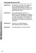
- Page 56: Περιγραφή διακοπτών DIL Διακόπτης 4: Εάν ρυθμιστεί σε On/Off, τόσο η θέρμανση όσο και η ψύξη λειτουργούν με τρόπο εντός/εκτός. Εάν ρυθμιστεί σε Chrono, τόσο η θέρμανση όσο και η ψύξη λειτουργούν με χρονοαναλογικό τρόπο. Διακόπτης 3: Είναι ενεργοποιημένος μόνο εάν ο διακόπτης 4 είναι ρυθμισμένος σε Chrono. Αυτός ο διακόπτης προσδιορίζει τον αριθμό των κύκλων ανά ώρα που θα επιβάλει στο σύστημα ο θερμοστάτης. Διακόπτης 2: Επιτρέπει την επιλογή κλίμακας θερμοκρασίας Κελσίου ή Φαρενάιτ. Διακόπτης 1: Δεν χρησιμοποιείται σ’ αυτό το μοντέλο.
- Page 57: Εγκατάσταση θερμοστάτη σε πίνακα ελέγχου Για την εγκατάσταση του θερμοστάτη στον πίνακα τοίχου, ευθυγραμμίστε τα αυτιά στο πάνω μέρος του θερμοστάτη με τα ανοίγματα στον πίνακα τοίχου και περιστρέψτε τον θερμοστάτη προς τα κάτω, πιέζοντας σταθερά για να πιάσει το κλιπ ασφάλειας στον πίνακα τοίχου. Ασφάλιση και περιορισμός Για να ασφαλίσετε ή να περιορίσετε το εύρος ρύθμισης, στρέψτε το δίσκο στο 3 και αφαιρέστε το κουμπί. Τοποθετήστε τα ελατήρια ασφάλισης στο πίσω μέρος του δίσκου στην επιθυμητή θέση και επανατοποθετήστε το κουμπί αφού βεβαιωθείτε ότι ο αριθμός 3 στο δίσκο είναι ευθυγραμμισμένος με το σημάδι αναφοράς στο περίβλημα.
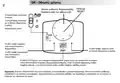
- Page 58: Οδηγίες χρήσης Πλήκτρο RESET Δίσκος ρύθμισης θερμοκρασίας, διαβάστε από την οθόνη LCD Ο ανεμιστήρας λειτουργεί συνεχώς Ο ανεμιστήρας λειτουργεί με τη ζήτηση θερμότητας ή ψύξης Η LED ανάβει πράσινη όταν ενεργοποιείται ο θερμοστάτης Η LED ανάβει πορτοκαλιά όταν λειτουργεί ο ανεμιστήρας Η οθόνη LCD δείχνει την υπάρχουσα θερμοκρασία χώρου Κατά τη ζήτηση θέρμανσης ανάβει σύμβολο φλόγας Σημείωση: Εάν είναι αναγκαίο να επαναφερθεί ο μικροεπεξεργαστής, χρησιμοποιήστε μη μεταλλικό ραβδάκι.
- Page 59: Instrukcja instalacji Produkt ten powinien być instalowany wyłącznie przez wykwalifikowanego elektryka lub instalatora ogrzewania. Montaż należy przeprowadzać zgodnie z aktualnymi przepisami dotyczącymi przewodów elektrycznych IEEE. Zakres temperatur, grzanie 5-30°C Zmiana temperatury - Chłodzenie na grzanie - Grzanie na chłodzenie Stan pracy termostatu: wyłączony/praca automatyczna z wentylatorem Zasilanie 30 Vac ± 15%, 50/60Hz Wyjścia przekaźnika, grzanie/chłodzenie i wentylator. Wymiary (mm) 110 dł., 90 wys., 40 szer. Zgodność z normą EN60730-1-9 Dokładność regulacji ±1°C
- Page 60: Opis urządzenia Termostat ten zaprojektowany jest do stosowania w systemach wyposażonych w klimakonwektory wentylatorowe obsługiwane przez 1-rurowy centralny system zmiany. Termostat ten steruje działaniem napędzanego silnikiem elektrycznym zaworu, który podczas okresów grzania otwiera się, gdy wymagane jest ciepło, a podczas okresów chłodzenia otwiera się, gdy wymagane jest chłodzenie. Zmiana z grzania na chłodzenie dokonywana jest automatycznie przez pomiar temperatury rury przepływowej. Jeśli temperatura przepływu przekroczy 30º C, termostat ten działa jak termostat grzewczy, a jeśli temperatura jest niższa niż 16º C, wtedy termostat działa jak termostat chłodzący. Jest niezmiernie ważne, aby obwód, w którym umieszczony jest czujnik, nie był zamknięty i aby woda krążyła przez rurę cały czas. Może to wymagać zastosowania zaworu obejściowego pomiędzy systemem przepływu i powrotu na końcu każdego obwodu. Instalacja Najpierw usuń pokrywę z tylnej części urządzenia. Aby zamontować przewód, w lewym górnym rogu pokrywy musi znajdować się wolny obszar o wymiarach przynajmniej 50 mm powyżej i 100 mm poniżej pokrywy.
- Page 61: Zamontuj urządzenie w odległości około 1,5 m od podłogi, z dala od przeciągów oraz źródeł ciepła, takich jak grzejniki, otwarty ogień czy bezpośrednie światło słoneczne. Miejsce umieszczenia czujnika rurowego. Przymocuj czujnik do rury zasilającej przy użyciu dostarczonej opaski mocującej. Jest niezmiernie ważne, aby obwód, w którym umieszczony jest czujnik nie był zamknięty i aby woda krążyła przez rurę cały czas. Może to wymagać zastosowania zaworu obejściowego pomiędzy systemem przepływu i powrotu na końcu każdego obwodu.
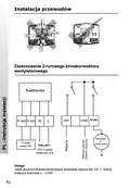
- Page 62: Instalacja przewodów Zastosowanie 2-rurowego klimakonwektora wentylatorowego Elektronika Czujnik rurowy PS1 Uwaga: Jeżeli grzanie/chłodzenie/wentylator posiadają wyjścia dla 230 V, należy połączyć końcówki L – COM
- Page 63: Instrukcja Przed ponownym zamocowaniem termostatu do płyty naściennej, przełączniki DIL na tylnej stronie urządzenia muszą być ustawione w wymaganej pozycji. Opcje przełącznika DIL pokazane w pozycji nastawienia fabrycznego (wszystkie przełączniki w pozycji włączonej). Sw On ON/OFF (Wlaczone/Wylaczone) CHRONO (Czasowy)
- Page 64: Opisy przełączników DIL Przełącznik 4: Jeżeli jest nastawiony na On/Off, zarówno grzanie, jak i chłodzenie działa w trybie On/Off. Jeżeli jest nastawiony na tryb Chrono, zarówno grzanie, jak i chłodzenie działa w trybie chronoproporcjonalnym. Przełącznik 3: Jest aktywny tylko wtedy, gdy przełącznik 4 jest ustawiony na tryb Chrono. Określa ilość cykli na godzinę, które termostat będzie wymuszał na systemie. Opcje obejmują trzy 20-minutowe cykle lub sześć cykli 10-minutowych. Przełącznik 2: Pozwala na wybór skali temperatury w ºC lub ºF. Przełącznik 1: Nie stosowany w tym modelu.
- Page 65: Montaż termostatu na płycie naściennej Aby zamontować termostat na płycie naściennej, należy ustawić termostat pokrętłem do góry i wykorzystując otwory w płycie naściennej zawiesić na zawiasach. Aby zablokować lub ograniczyć zakres nastawienia temperatury, należy obrócić tarczę nastawną na pozycję 3 i wyjąć pokrętło. Umieścić sprężyny blokujące w tyle tarczy w żądanej pozycji i ponownie zamontować pokrętło.
- Page 66: Instrukcja użytkownika Przycisk resetowania (RESET) Tarcza nastawiania temperatury, nastawioną wartość pokazuje wyświetlacz LCD. Wentylator pracuje w sposób ciągły. Wentylator pracuje, gdy wymagane jest grzanie lub chłodzenie. Termostat jest wyłączony. Dioda zielona świeci, gdy termostat jest zasilany. Zielona dioda świeci się, gdy wymagane jest grzanie lub chłodzenie. Dioda pomarańczowa świeci, gdy pracuje wentylator. Wyświetlacz LCD pokazuje aktualną temperaturę w pokoju. Uwaga: Gdyby z jakiegoś powodu konieczne było zresetowanie mikroprocesora, przycisk do resetowania umieszczony jest poniżej tarczy nastawczej.
- Page 67: Montavimo instrukcijos Šį gaminį prijungti gali tik kvalifikuotas elektrikas arba kompetentingas šildymo sistemos instaliuotojas. Prijungimas turi būti suderintas su IEEE elektros laidų montavimo reglamento dabartine redakcija. Temperatūros diapazonas, šildymas 5-30°C. Temperatūros keitimas: iš vėsinimo į šildymo režimą, iš šildymo į vėsinimo režimą. Maitinimas 30 Vac ± 15%, 50/60Hz. Matmenys (mm): 110 plotis, 90 aukštis, 40 gylis. Atitinka standartus EN60730-1-9. Nominali impulso įtampa 0.5Kv. Tiksli temperatūra 75°C.
- Page 68: Gaminio aprašymas Termostatas skirtas naudoti sistemose su ventiliatoriniais konvektoriais, prijungtais prie 2 vamzdžių pagrindinės keitimo sistemos. Termostatas reguliuoja vožtuvo su pavara veikimą, atidarydamas vožtuvą šildymo ir vėsinimo periodais, kai reikia aktyvuoti atitinkamą temperatūrą. Šildymo režimas į vėsinimo perjungiamas automatiškai, išmatavus įtekančios srovės vamzdyje temperatūrą. Jei srovės temperatūra yra didesnė nei 30°C, įrenginys veikia kaip šildymo termostatas, o jei mažesnė nei 16°C – kaip vėsinimo termostatas. Būtina įsidėmėti, kad grandinė, kurioje yra vamzdžio daviklis, nebūtų uždaryta ir kad visąlaik per daviklį cirkuliuotų vanduo. Montavimo instrukcijos Iš pradžių nuimkite sienos plokštelę nuo prietaiso galo. Nuo viršutinio kairiojo sienos plokštelės kampo iki dešiniojo krašto turi būti mažiausiai 50 mm viršuje ir 100 mm apačioje tarpas, kad būtų galima sumontuoti jungiamą kištuku modulį.
- Page 69: Pritvirtinkite prietaisą apie 1,5 m aukštyje nuo grindų, atokiau nuo skersvėjo ar šilumos šaltinių. Pritvirtinkite vamzdžio daviklį prie srovės įtekėjimo vamzdžio. Naudokite suspaudžiamąją juostą. Labai svarbu, kad grandinė, kurioje yra vamzdžio daviklis, nebūtų uždaryta. Visąlaik per daviklį turi cirkuliuoti vanduo. Gali tekti pritvirtinti papildomą vožtuvą tarp sistemos įtekėjimo ir grįžimo.
- Page 70: Laidai 2 vamzdžių ventiliatorinio konvektoriaus pritaikymas Pastaba: Jei šildymo/vėsinimo/vėdinimo režimas – galia yra 230 V, jungtys L – COM 70
- Page 71: Paleidimas Prieš tvirtinant termostatą prie sieninės plokštės, DIL reikia perstatyti prie įrenginio nugarėlės ir sureguliuoti pagal norimą padėtį. DIL perjungiklio padėtys, gamyklinės reguliavimo padėtys.
- Page 72: DIL jungiklių aprašymai 4 jungiklis: Nustačius On/Off, ir šildymo, ir vėsinimo funkcijos veikia on/off režimu. Nustačius Chrono, abi – šildymo ir vėsinimo funkcijos veikia laikui proporcingu režimu. 3 jungiklis: Veikia tik tuomet, kai 4 jungiklis yra nustatytas į Chrono padėtį. Šiuo jungikliu nustatomas termostato veikimo sistemoje ciklų skaičius per valandą; galima pasirinkti tris 20 minučių trukmės arba šešis 10 minučių trukmės ciklus. 2 jungiklis: Pasirenkama matavimo skalė – pagal Celsijų arba pagal Farenheitą. Šiame modelyje nenaudojamas.
- Page 73: Termostato tvirtinimas prie sienos Jei norite pritvirtinti termostatą prie sienos, pridėkite termostato viršuje esančias kilpeles prie sienos kiaurymių ir, švelniai spausdami žemyn, patikrinkite, ar termostato laikiklis užsifiksavo. Blokavimas ir ribojimas Jei norite užfiksuoti ar apriboti parametrų nustatymus, pasukite rankenėlę prie 3 žymos ir ją nuimkite. Nustatykite į norimą padėtį užrakto spyruokles, kurios yra reguliatoriaus antrojoje pusėje, ir perstatykite rankenėlę (skaičius 3 turi sutapti su korpuso žyma).
- Page 74: Informacija vartotojui Temperatūros nustatymo skalė; nustatytą skaičių matysite LCD. Ventiliatorius veikia nepertraukiamai. Ventiliatorius veikia šildymo ar vėsinimo režimu. Termostatas išjungtas; LED indikatorius dega žaliai, kai termostatas įjungtas. Šildymo arba vėsinimo metu dega LED indikatorius žaliai. LED indikatorius dega oranžine spalva, kai veikia ventiliatorius. LCD ekrane rodoma dabartinė patalpos temperatūra. Jei rankenėlė yra pasukta prie laiko žymos, rodoma momentinė temperatūra. Šildymo metu įsižiebia liepsnelės pavidalo indikatorius, o jei patalpa vėsinama, įsižiebia snaigė. Jei būtina atstatyti mikroprocesorių, spauskite atstatymo mygtuką, kuris yra už reguliatoriaus.
- Page 75: Istruzioni per l’uso L’installazione di questo prodotto deve essere effettuata esclusivamente da elettricisti qualificati o da installatori specializzati in impianti di riscaldamento, in conformità con le ultime prescrizioni della normativa IEEE. Caratteristiche del termostato Intervallo temperatura, riscaldamento 5-30°C Selettore disinserimento/funzionamento automatico termostato e inserimento ventilatore Alimentazione 30 Vac ± 15%, 50/60Hz Uscite relè, riscaldamento/raffreddamento e ventilatore Dimensioni (mm) 110 larghezza, 90 altezza, 40 profondità Standard di progetto EN60730-1-9 Tensione nominale impulsi 0.5Kv Precisione temperatura ±1°C
- Page 76: Descrizione prodotto Il termostato è progettato principalmente per l’impiego in sistemi a fan-coil con un sistema di commutazione centralizzato a tubi. Il termostato comanda l’azionamento della valvola motorizzata che, durante i periodi di riscaldamento, si apre per consentire il riscaldamento e che, durante i periodi di raffreddamento, si apre per consentire il raffreddamento. La commutazione dalla funzione di riscaldamento a quella di raffreddamento avviene automaticamente mediante rilevamento della temperatura della tubazione di portata. Se la temperatura supera i 30°C il termostato funziona come unità di riscaldamento, mentre se la temperatura è inferiore a 16°C il termostato funziona come unità di raffreddamento. È essenziale che il circuito nel quale è alloggiato il sensore della tubazione non sia chiuso e che l’acqua circoli costantemente oltre il sensore. Questo può richiedere il montaggio di una valvola di bypass tra la portata del sistema e il ritorno al termine di ciascun circuito. Installazione Rimuovere innanzitutto la piastra a parete dal retro dell’unità. Per il montaggio del modulo plug-in, è necessario che in corrispondenza dell’angolo superiore sinistro della piastra sia disponibile uno spazio libero di almeno 50 mm verso l’alto e 100 mm verso il basso.
- Page 77: Installarlo ad un’altezza di circa 1,5 m da terra, al riparo da correnti d’aria o fonti di calore. Fissare il sensore alla tubazione di portata utilizzando l’apposita fascetta di fissaggio fornita. È essenziale che il circuito nel quale è alloggiato il sensore della tubazione non sia chiuso e che l’acqua circoli costantemente oltre il sensore. Questo può richiedere il montaggio di una valvola di bypass tra la portata del sistema e il ritorno al termine di ciascun circuito.
- Page 78: Cablaggio Applicazioni con fan-coil a 2 tubi Elettronica Ventilatore a 1 velocità Sensore tubazione PS1 230 V c.a. fissa 3A Nota: Se le uscite RISCALDAMENTO/RAFFREDDAMENTO/VENTILATORE sono a ꢀ30 V, collegare i terminali L – COM
- Page 79: Messa in servizio Prima di rimontare il termostato sulla staffa a parete, occorre impostare gli interruttori DIL sul retro dell’unità, sui valori desiderati. Opzioni interruttori DIL, mostrate nelle posizioni di impostazione di fabbrica.
- Page 80: Descrizione interruttori DIL Interruttore 4: Se impostato su On/Off, il riscaldamento e raffreddamento operano entrambi in modalità on/off. Se impostato su Chrono, il riscaldamento e raffreddamento operano entrambi in modalità di regolazione crono-proporzionale. Interruttore 3: Attivo solo se l’interruttore 4 è impostato su Chrono. Questo interruttore determina il numero di cicli all’ora che il termostato impone al sistema, le opzioni selezionabili prevedono tre cicli da 30 minuti o sei cicli da 10 minuti. Interruttore 2: Consente di selezionare la scala di temperatura Celsius o Fahrenheit. Interruttore 1: Non usato su questo modello.
- Page 81: Montaggio termostato sulla staffa a parete Per montare il termostato sulla staffa a parete, allineare le linguette sulla parte superiore del termostato con le aperture della staffa e ruotare il termostato verso il basso, premendo saldamente per agganciare il fermo di fissaggio sulla staffa. Bloccaggio e esclusioni Per bloccare o escludere l’intervallo di impostazione ruotare il pomello di regolazione in posizione 3 e staccare il pomello. Posizionare le molle di bloccaggio sul retro del pomello nella posizione desiderata e rimontare il pomello facendo coincidere il numero 3 del pomello con il contrassegno previsto sull’alloggiamento.
- Page 82: Istruzioni per l’utente Pomello di regolazione temperatura Display LCD Funzionamento continuato del ventilatore Funzionamento del ventilatore in base alle richieste di riscaldamento o raffreddamento Accensione LED di colore verde all’alimentazione del termostato Accensione LED di colore verde durante la richiesta di riscaldamento o raffreddamento Accensione LED di colore arancione all’azionamento del ventilatore Il display LCD mostra l’effettiva temperatura ambiente a meno che non venga azionato il pomello. Durante il riscaldamento si illumina il simbolo della fiamma, mentre durante il raffreddamento si illumina il simbolo del fiocco di neve. Se fosse necessario resettare il microprocessore, è previsto il pulsante di RESET.
- Page 83: Page 83