STELPRO STCP MULTIPLE PROGRAMMING ELECTRONIC THERMOSTAT User Guide


USER’S GUIDE
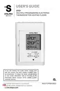
STCP
MULTIPLE PROGRAMMING ELECTRONIC
THERMOSTAT FOR HEATING FLOORS
If you are viewing this guide online, please note
that this product has been slightly modified since
its introduction. To obtain the guide corresponding
to your model (fabrication date at the back of the
@
thermostat before January 2016), please contact
customer service.
For further information or to consult
ww.stelpro.com
INSSTCP5MA0622

| General | Details |
|---|---|
| Name | STELPRO STCP MULTIPLE PROGRAMMING ELECTRONIC THERMOSTAT User Guide |
| Make | StelPro |
| Language | English |
| Filetype | PDF (Download) |
| File size | 0.45 MB |


STELPRO STF362NP Floor Heating Thermostat Owner’s Manual

STELPRO ST302P Programmable Electronic Thermostat Owner’s Manual

STELPRO SAT402ZB Smart Thermostat User Guide

STELPRO ST252NPFF Non-Programmable Electronic Thermostat Owner’s Manual

STELPRO ST402PFF Programmable Electronic Thermostat Owner’s Manual

STELPRO ASMC402 Maestro Zigbee Smart Programmable Thermostat User Guide

STELPRO SIBTE12C Electronic Thermostat Owner’s Manual

STELPRO STZW402+ Electronic Thermostat for The Smart Home Owner’s Manual

STELPRO SIBTE13F Electronic Thermostat User Guide

STELPRO STCP Floor Heating Thermostat Multiple Programming User Guide

STELPRO STCP MULTIPLE PROGRAMMING ELECTRONIC THERMOSTAT User Guide Overview
Summary of Contents
- Page 1: User's guide for the multiple programming electronic thermostat for heating floors. This product has been slightly modified since its introduction. To obtain the guide corresponding to your model, please contact customer service. For further information or to consult this guide online, please visit our website.
- Page 2: Warning Before installing and operating this product, the owner and/or installer must read, understand and follow these instructions and keep them handy for future reference. If these instructions are not followed, the warranty will be considered null and void. The following instructions must be adhered to in order to avoid personal injuries or property damages. All electric connections must be made by a qualified electrician, according to the electrical and building codes effective in your region. Do not connect this product to a supply source other than 120 VAC, 208 VAC or 240 VAC. You must regularly clean dirt accumulations on or in the thermostat. Do not use fluid to clean thermostat air vents. When a part of the product specification must be changed to improve operability or other functions, priority is given to the product specification itself. The actual product and packaging, as well as the name and illustration, may differ from the manual. The screen/LCD display shown as an example in this manual may be different from the actual screen/LCD display.
- Page 3: The STCP electronic thermostat can control heating floors with a resistive load ranging from 0 A to 16 A at 120/208/240 VAC. It features an easy user interface and can manage up to four programming periods a day. Floor mode is ideal for areas where a hot floor is desired, such as in a bathroom. Ambient mode provides a stable air temperature and is suitable for large, frequently occupied rooms like kitchens, living rooms, or bedrooms. Factors that cause variations in ambient temperature include large windows and other heat sources. The thermostat is not compatible with electrical currents higher than 16 A or with inductive loads and central heating systems.
- Page 4: Parts supplied include one thermostat, two mounting screws, four solderless connectors suitable for copper wires, and one floor sensor. The thermostat must be mounted on a connection box, approximately 1.5 m (5 feet) above the floor level, on a wall section free from pipes or air ducts. Avoid installing the thermostat in locations where temperature measurements could be affected, such as near windows, external walls, or doors leading outside. Do not expose the thermostat directly to light or heat sources like the sun, lamps, or fireplaces. Ensure the thermostat is not placed close to air outlets, concealed ducts, or chimneys. Avoid locations with poor air flow or frequent air drafts. Refer to the installation guide of your heating floor for sensor installation. Cut off power supply on lead wires at the electrical panel to avoid electric shock. Ensure the thermostat is installed on a junction box located in an uninsulated wall. Make sure the air vents of the thermostat are clean and free of obstructions.
- Page 5: Using a screwdriver, loosen the screw retaining the mounting base and front part of the thermostat. Remove the front part of the thermostat from the mounting base by tilting it upward. Align and secure the mounting base to the connection box using the two screws supplied. Route wires coming from the wall through the hole of the mounting base and make the required connections using the “Four-wire installation” figure. A pair of wires (black) must be connected to the power source (120-208-240 VAC). Another pair (yellow) must be connected to the heating cable. For connections with aluminum wires, you must use CO/ALR connectors. Thermostat wires do not have polarity, meaning that any wire can be connected.
- Page 6: Connect the wires of the floor temperature sensor at the indicated location behind the thermostat. Reinstall the front part of the thermostat on the mounting base and tighten the screw at the bottom of the unit. Turn on the power. Set the thermostat to the desired setting.
- Page 7: Operation Ambient temperature (Ambient mode) Floor temperature (Floor mode) Security mode First start-up: The thermostat is initially in manual modes. The temperature is displayed in degrees Celsius with a standard factory set point adjustment of 21°C. The hour displays --:-- and must be adjusted before switching to Auto or Pre Prog mode. The maximum floor temperature is limited to 28°C. Ambient and floor temperature: The figures displayed indicate the ambient temperature, ±1 degree. The figures displayed indicate the floor temperature, ±1 degree. Both temperatures can be displayed in degrees Celsius or Fahrenheit.
- Page 8: Temperature set points indicate the ambient or floor temperature settings, displayed in degrees Celsius or Fahrenheit. To adjust the set point, press the + button to increase or the - button to decrease it by increments of 1 degree. To quickly scroll through set point values, press and hold the button. The maximum floor temperature is maintained at less than 28°C (82°F) to avoid overheating and potential damage. The adjustment procedure for the hour and day of the week involves pressing the Day/Hr button in any mode. The day of the week can be adjusted using the + or - button, confirmed by pressing the Mode or Day/Hr button. The hour can be adjusted similarly, with confirmation required after setting. Minutes can also be adjusted using the + or - button, followed by confirmation. After adjustments, the thermostat returns to the previous mode.
- Page 9: At any time, you can exit the adjustment mode of the day and the hour by pressing down the Exit button or by not pressing any button during 1 minute. In case of a power failure, the thermostat is self-sufficient for 2 hours. If the failure lasts less than 2 hours, the thermostat saves the adjustment of the hour and the day of the week. When the power is restored after an extensive failure (more than 2 hours), the hour and the day of the week are recovered, but you must update them. The thermostat can display the ambient temperature and the set point in degrees Celsius or Fahrenheit. To switch from degrees Celsius to degrees Fahrenheit, simultaneously press down the + and - buttons for more than 3 seconds until the icon blinks. Press down the + button to switch from degrees Celsius to degrees Fahrenheit, and conversely. When the adjustment is completed, press down the Exit button or do not press down any button during 5 seconds to exit the adjustment function. This adjustment can be done from any of the three principal modes. From the Manual mode, you can manually adjust the thermostat set point by pressing down the + or - buttons to increase or decrease the value.
- Page 10: To quickly scroll through the set point values, press and hold down the button. From manual mode, the set points can range between 3 and 35°C and can only be adjusted by increments of 1°C. The thermostat will turn off if the set point is lowered below 3°C, and the set point value displayed will be --. The standard factory set point adjustment is 21°C in manual mode. You must adjust the hour before switching to other modes. To switch from manual mode to automatic mode, press down the Mode button. From the automatic mode, the thermostat adjusts the set points according to the programmed periods. If no data is entered, the thermostat acts as in manual mode with a standard factory set point adjustment of 21°C. It is possible to program 4 periods a day, meaning that the set point can change automatically up to 4 times a day. From this mode, the screen displays the temperature, the set point, the hour, the day of the week, and the current programmed period number.
- Page 11: To access the programming mode, press down the day of the week button that you want to program. Select the period number (1 to 4) that you want to program using the + or - button. The two figures representing the hour blink to indicate that you can adjust them using the + or - button. After confirmation, the figures representing the minutes blink. The period set point blinks and you can adjust it using the + or - button. After set point confirmation, the programming is completed. At the end of period 4 programming, you automatically exit the programming mode. At any time, you can exit the programming mode using one of three methods. You must confirm the period by pressing down the Mode button. The minutes can only be adjusted by increments of 15 minutes.
- Page 12: Press down the button of another day to program it. If you do not press down any button for more than 1 minute, the thermostat will exit the Programming mode. This mode enables the room to reach the selected temperature at the programmed hour by starting or stopping the heating before this time. The thermostat estimates the delay required to reach the set point of the next period at the programmed hour. The anticipated start icon will blink when the anticipated start of the next period begins. To activate or deactivate the anticipated start, the thermostat must be in Auto or Pre Prog mode. The anticipated start icon is displayed or hidden to indicate the activation or deactivation of the mode. If you modify the temperature set point manually when these modes are activated, the anticipated start of the next period will be cancelled. The anticipated start is initially activated when you enter the Automatic or Preprogrammed mode. You must deactivate it following the above procedure if needed.
- Page 13: Copying programming allows you to apply the programming of one day to other days. To copy programming day by day, press down the source day button and select destination days one by one. Release the source day button after all selections are completed to apply the programming. To copy programming in block, press down the source day button and the last day of the block. Hold the buttons for 3 seconds to activate the block copy. The block order is always increasing; for example, copying from Thursday to Monday includes Friday to Monday. To erase a programming period, access the Programming mode by pressing the corresponding day button. Select the period to erase using the + or - button. You do not need to press the Mode button to confirm the selection, but it will not affect the erasing process.
- Page 14: Simultaneously press down the + and – buttons to erase the period programming. The hour displays --:-- and the set point displays -- to indicate that the programming is erased. The erased period number blinks and you can select another period to be erased or exit the Programming mode. The Preprogrammed mode allows an automatic programming of the thermostat. 252 preprogrammings have been defined for mode and 252 for mode. This mode gives you the possibility to quickly program the thermostat using preprogrammings commonly used without having to do it manually. It is possible, at any time, to manually adjust the set point from the Automatic mode. If the set point is lowered to off (--), the programming will not be effective. From this mode, the screen displays the temperature, the set point, the hour, the day of the week, and the current number of the preprogramming. You can only access the Preprogramming mode when the thermostat is out of any programming or adjustment function. Make sure to choose the preprogrammings corresponding to the right mode according to the attached tables.
- Page 15: The Pre Prog icon and saved selected preprogramming are displayed. This preprogramming can range between 0 and Z1. From the Pre Prog mode, you can choose the first 10 preprogrammings by pressing and releasing the Pre Prog button. To choose advanced preprogrammings, press down the Pre Prog button for 5 seconds. The letter indicator blinks and you can adjust it by pressing down the + or - button. Once the letter is chosen, you must validate your choice by pressing down the Mode button. If you do not press down any button for more than one minute or press the Exit button, the thermostat exits the adjustment function and saves the current choice. The view of the selected preprogramming is made in a way similar to the Auto mode programming. It is impossible to modify the preprogramming. Press down the button corresponding to the day to view the selected day. When the selected day is displayed, the icon and period number blink.
- Page 16: Choose the period number (1 to 2) to view using the + or - button. For each period, the hour and set point are displayed. You can also press down the Mode button to switch to period 2. At any time, you can exit the View mode using one of these 3 methods: press down the button of the day you are viewing, press down another day to view it, or press down the Exit button. If you do not press down any button during 1 minute, the thermostat quits the view mode. To switch from the mode to the mode, press down the A/F button when you are not in any adjustment mode. If the thermostat fails to detect the presence of a floor sensor, it will automatically revert to safe mode at a set point of 21°C. If you want to use the STCP thermostat with a temperature sensor already installed in the floor, you must contact customer service to validate compatibility.
- Page 17: Temperature control is managed by the thermostat with high accuracy. A clicking sound is normal when the heating starts or stops due to the relay operation. The screen backlights when a button is pressed and turns off after 15 seconds of inactivity. Pressing the + or – button once will light up the screen without changing the set point value. The GFCI reduces the risk of electric shock by detecting leakage currents of 5mA. If a defect is detected, the GFCI lights up and deactivates the screen and heating system. The GFCI can be reinitialized by pressing the Test button or disconnecting the thermostat. Monthly verification of the GFCI installation and operation is important. The GFCI verification procedure involves increasing the temperature set point and pressing the Test button. Successful tests are indicated by a red light and the display showing the temperature.
- Page 18: Reinitialize the ground-fault circuit interrupter by pressing the test button again, which turns off the red indicator. If the red indicator lights up and the display shows E4, disconnect the heating system and contact customer service. A red indicator with only the time displayed indicates a ground-fault; disconnect the heating system and contact customer service. Security mode sets a maximum temperature that cannot be exceeded, but the set point can be lowered. Activating Security mode requires exiting any adjustment mode and pressing the + and - buttons simultaneously for 10 seconds. After 3 seconds of pressing the buttons, the icon blinks, displaying the software version and date. Once Security mode is activated, the icon will display, and the buttons can be released. To deactivate Security mode, cut off the power supply to the thermostat and wait at least 30 seconds.
- Page 19: Restore the power supply to the thermostat. The icon will blink during a maximum of 5 minutes, indicating that you can deactivate the Security mode. Simultaneously press down the + and - buttons for more than 10 seconds. The icon will then be hidden indicating that the Security mode is deactivated. The thermostat saves some parameters in its nonvolatile memory to recover them when power is restored. These parameters include the current Man/Auto/Pre-Prog mode, the hour and the day of the week, and the last effective set point. The thermostat can detect a power failure. Adjustments are automatically saved in volatile memory and recovered when power is restored. The thermostat enters a very low consumption mode and only displays the hour and day of the week during a power failure. The thermostat is self-sufficient for 2 hours. If the power failure lasts less than 2 hours, the thermostat saves the adjustment of the hour. When power is restored after an extensive failure, it recovers the last mode and various adjustments that were effective when the failure occurred. The hour and the day of the week are also recovered, but you must update them. The set point will be the same as what was active when the failure occurred. During the first half hour of the failure, the hour and day of the week are displayed. After half an hour, the screen turns off to ensure energy saving.
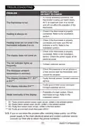
- Page 20: Troubleshooting In normal operating conditions, the thermostat housing can reach nearly 40°C at maximum load. It is normal and will not affect the operation of the thermostat. Check if the thermostat is properly connected. Refer to the installation section. Heating does not run even if the thermostat indicates it is on. Check the power supply at the electrical panel. The display does not come on. Check the presence of an air stream or a heat source near the thermostat, and correct the situation. The displayed ambient temperature is incorrect. Faulty thermal sensor. Contact customer service. Possibility of a bad contact. Check thermostat wirings. If you do not solve the problem after checking these points, cut off the power supply at the main electrical panel and contact customer service.
- Page 21: Technical specifications include supply voltage of 120/208/240 VAC, 50/60 Hz. The maximum electrical current with a resistive load is 16 A. The power output is 3840 W at 240 VAC, 3330 W at 208 VAC, and 1920 W at 120 VAC. The temperature display range is from 0 °C to 40 °C (32 °F to 99 °F) with a resolution of 1 °C (1 °F). The temperature set point range in ambient mode is 3 °C to 35 °C (37 °F to 95 °F) and in floor mode is 3 °C to 28 °C (37 °F to 82 °F). Temperature set point increments are 1 °C (1 °F). Storage temperature ranges from -30 °C to 50 °C (-22 °F to 122 °F). The certification is cETLus.
- Page 22: Limited warranty This unit has a 3-year warranty. If at any time during this period the unit becomes defective, it must be returned to its place of purchase with the invoice copy. In order for the warranty to be valid, the unit must have been installed and used according to instructions. If the installer or the user modifies the unit, he will be held responsible for any damage resulting from this modification. The warranty is limited to the factory repair or the replacement of the unit. The warranty does not cover the cost of disconnection, transport, and installation.

Honeywell N100 Series Non Programmable Thermostat Installation Guide

19810-102 Digital Room Thermostat Libra Auraton Weekly User Manual

Gelia ip24 1.5m Cable With Stepless Thermostat Instruction Manual

Honeywell T6/T6R Smart Thermostat User Guide

EPH CONTROLS 20221108 RF Cylinder Thermostat Instruction Manual

Danfoss TVM-H Thermostat Valve Owner’s Manual

BOSCH BCC110 Connected Control Wi-Fi Thermostat User Manual

TFC Group WFSTAT Wi-Fi Thermostat Instructions

SALUS CONTROLS T105 Digital Programmable Thermostat User Guide

bandary FC660 Smart Thermostat User Guide