BOSCH BCC110 Connected Control Wi-Fi Thermostat User Manual


Bosch Connected Control
BCC110 Wi-Fi Thermostat
Installation Guide & User Manual
Bosch-homecomfort.us

| General | Details |
|---|---|
| Name | BOSCH BCC110 Connected Control Wi-Fi Thermostat User Manual |
| Make | Bosch |
| Language | English |
| Filetype | PDF (Download) |
| File size | 1.41 MB |
 (1 votes, average: 5.00 out of 5)

BOSCH RT_II_230V Room Thermostat Instructions

BOSCH Smart Home Room Thermostat Instruction Manual

BOSCH BCC110 Connected Control Thermostat Instruction Manual

BOSCH RT20 RF Room Thermostat User Manual

BOSCH 6721807275 Smart Radiator Thermostat Installation Guide

BOSCH Thermostat atmosphere Smart Home 230 V Instruction Manual

BOSCH 8750000270 Radiator Thermostat II Smart Home Radiator Thermostat Instructions

BOSCH II 230V Room Thermostat Instruction Manual

BOSCH Radiator Thermostat Instructions

BOSCH BCC110 Thermostat User Guide

BOSCH BCC110 Connected Control Wi-Fi Thermostat User Manual Overview
Summary of Contents
- Page 1: Bosch Connected Control BCC110 Wi-Fi Thermostat Installation guide & user manual
- Page 2: Installation guide BCC110 device user manual BCC app user manual Compatibility Thermostat main screen Initial setup Advanced settings Troubleshooting Wiring diagrams Additional features
- Page 3: Meet the Bosch Connected Control (BCC110 Thermostat) The Bosch Connected Control BCC110 Thermostat is compatible with the majority of 24V heating and cooling equipment to help you save energy and money. Easily control your home's temperature from the full color 5” touchscreen display, the Bosch EasyAir app, or your voice with the Bosch Connected Control Alexa Smart Home Skill. Connect to your HVAC equipment from anywhere. Access your local forecast from your thermostat. Large screen for ease-of-use and offline access. Get alerts when it's time to replace your system's filter. Follows preset or user-defined schedules. Compatible with the majority of HVAC systems (requires C-wire). Works with Google Assistant or Amazon Alexa.
- Page 4: Compatibility A C-wire (common wire) is required to power the unit. Two wire systems are not supported. The Bosch Connected Control BCC110 Wi-Fi Thermostat works with most 24V systems, including gas, oil, propane, electric, forced air, variable speed, heat pump, and radiant. The BCC110 is not compatible with other Bosch Boiler controls, such as the Logamatic. The thermostat cannot support line voltage thermostats, electric baseboard heaters, proprietary communicating thermostats, millivolt systems, or remote sensors. Professional installation is recommended for certain systems. Self-support videos can be found on our website.
- Page 5: Installation overview Included in the box Tools you will need BCC110 Wi-Fi thermostat Screws (2) and anchors (2) Flathead screwdriver Medium Phillips screwdriver Smartphone Jumper wire Bosch EasyAir app
- Page 6: Thermostat installation involves several key steps. Turn off power to your HVAC system using the master equipment switch or circuit breaker box. Failure to turn off the power may result in electrical shock and/or damage to the equipment. Confirm that your old thermostat does not contain line voltage wiring. Adjusting the temperature on your old thermostat can help verify that the system is off. If the system does not turn on within 5 minutes, the power is successfully off. If you see any wire nuts, the BCC110 may not work with your system. Consider contacting a professional if you are unsure about your options.
- Page 7: Take a picture of the existing wiring. Make sure that you can clearly read the terminal labels and see which wires are connected to which terminals from your photo. Disconnect the wires from the old thermostat and remove the wall plate using a screwdriver. Wrap a pen or pencil around the wires to prevent them from falling back into the wall. You can also use the wire labels we have provided you to correctly label each wire based on the terminal where it is connected. Confirm you have a C-wire connected to your old thermostat wall plate. If you do not have a C-wire connected to your old thermostat, please contact a professional for assistance. Pull thermostat wires through the hole in the center of the BCC110 wall plate. Mark the location of the mounting screws. Use the BCC110 Wall Plate as a reference guide to mark the mounting holes.
- Page 8: Thermostat installation involves several key steps. Insert each wire into the corresponding terminal and close each terminal using a flat head screwdriver. Use the image of your old thermostat wiring or the wire labels as a reference for where to place each wire. Be sure that you insert each wire, one by one, and then immediately close the terminal. Drill two 7/32” holes where you marked the location of the mounting screws and then insert the wall anchors provided. Check if the wall plate is level and insert screws. Make sure your new wall plate is level and insert the included screws from the package. Mount your new wall plate to the wall using a Phillips head screwdriver. If you are unsure of the terminal names on the BCC110 Wall Plate, refer to the BCC110 Terminal Key on the next page. Small flat head screwdriver and Phillips head screwdriver are needed for installation.
- Page 9: BCC110 Terminal After all wires are securely connected, gently push any excess wires back into the hole in the wall. Attach the BCC110 thermostat to the BCC110 wall plate. The color of your wires may not be the same as shown. Emergency heat activated at W/E. Single-stage auxiliary heat activated at W2/AUX. Only to be used with Bosch WSHP.
- Page 10: Thermostat installation steps are outlined. Turn on the power to your HVAC system using the master equipment switch or circuit breaker box. The thermostat will power on and display a Bosch logo and loading bar. Download the Bosch EasyAir app to set up your new BCC110 thermostat. Your BCC110 thermostat is not yet configured to your home’s HVAC system. Go to the Apple App Store or Google Play Store to download the app and create an account. After loading completes, the thermostat will display a specific screen. Three ways to download the Bosch EasyAir app are provided. Search for Bosch Connected Control or BCC110 in the app stores to download. Visit the Bosch website or scan the QR code for additional download options.
- Page 11: Initial setup involves downloading the Bosch EasyAir App and accepting the terms and conditions. User account setup requires entering an email address and password for registration. Select your role as Homeowner to begin creating your profile. Input your first and last name during the setup process. Verify your phone number by entering the verification code received via text. Once completed, your profile will be successfully created. To add a device, choose the appliance you want to add, such as BCC110. Initiate the initial setup by clicking OK on your thermostat. Find the MAC ID and temporary verification code in the Wi-Fi settings on your thermostat. Follow the on-screen instructions to connect your smartphone to the device.
- Page 12: If you have a furnace Initial setup for a quick and easy way to begin using your new smart thermostat. Select Fossil Fuel and click the Next Arrow at the top right corner of the screen. Select Appliance or Thermostat depending on your personal preferences for fan control. Unit configuration involves selecting your home’s heating type, stage configuration for heating and cooling, and type of accessory if available. If you have a boiler, select Fossil Fuel and click the Next Arrow at the top right corner of the screen. Select your heat type according to the heating appliance located in your home. If you have a heat pump, select Heat Pump and click the Next Arrow at the top right corner of the screen. Configure the reversing valve for O (energized in cool) or B (energized in heat) and enable/disable Emergency Heat and/or Auxiliary Heat. If you have a dual fuel system, select Dual Fuel and click the Next Arrow at the top right corner of the screen. Follow the on-screen instructions to configure the fossil fuel fan control settings and the heat pump dual fuel changeover settings.
- Page 13: Use the Balance Point to set the outdoor temperature value for switching between heat pump and fossil fuel appliance. Above the balance point, the thermostat will use the heat pump for heating, and below it, the fossil fuel heating appliance. Use the Change over Delay to set the time the system will be off when changing between heating sources. Professional installation is recommended for humidifiers and dehumidifiers. In a dual fuel system, the BCC110 automatically enables auxiliary heating using the fossil fuel heating appliance. The BCC110 will stage up from heat pump to fossil fuel following the stage settings. If you have a humidifier, select it and follow the on-screen instructions for Evaporative or Steam options. If you have an electric system, select Electric and proceed. If you have a dehumidifier, select it and enable or disable Cool to Dehumidify as needed. Select your stage configuration according to the heating and cooling appliances in your home.
- Page 14: After you have successfully established a connection, your network name appears. If your thermostat is already registered to your account on your smart device, your User ID name appears. Follow additional instructions on the screen to complete setup. After completing the setup, download the Bosch EasyAir App from the Apple Store or Google Play Store. Create an account within the app and then add a device (BCC110) by following the on-screen instructions. If you are trying to connect to a hidden network, press the SSID button to bring up the SSID screen. Enter your SSID into the text box, then follow the on-screen instruction to complete the Wi-Fi setup. If this is a first time installation, follow the instructions in the App Setup section of this User Guide to register your thermostat to your smart device. The following may cause a failed connection to the device: Wi-Fi signal is too weak, 5 GHz Wi-Fi network is not supported, SSID contains space or non-ASCII characters, incorrect password, Wi-Fi is okay but your internet is unavailable, additional web authentication is not supported. For all smart devices that require access to the same thermostat, you must use the same account.
- Page 15: Initial setup involves registering your account by clicking the green Registration button. You can register a different account by following the steps in the App Setup section. To modify your schedule, choose the desired schedule or select No Schedule and click the Setup button. Home is the default schedule for your device, and you can add a different schedule using the Bosch EasyAir App. To set up daily periods, click on the Start Time bubble and use the Up/Down arrows to set the start time for the first period. If the device loses connection with the wireless network, it will attempt to reconnect automatically after 5 minutes, then every 15 minutes for the next 24 hours. Manual network reconfiguration will stop these attempts. You can set the heating setpoint for the first period by clicking the Heat bubble and using the Up/Down arrows. Similarly, set the cooling setpoint by clicking the Cool bubble and using the Up/Down arrows.
- Page 16: This schedule will be used to set your heating/cooling equipment to 2 periods with set points that can be manually adjusted. There is a 5 degree deadband required between heating and cooling setpoints to prevent equipment from short cycling. You are allowed a maximum of 8 periods per day. After you have set up one day of the week, use the Copy section to mirror the same daily schedule to other days of the week. During offline operations, only 2 schedules (Home and Vacation) are available. When a Wi-Fi connection is established, the list can be expanded up to 4 schedules. You can use this schedule to set your heating/cooling equipment to predefined set points. The device initially comes with a factory default schedule, which can be adjusted as necessary.
- Page 17: Initial Setup In the final step, the BCC110 provides a summary review of information that you have entered into the thermostat. You will be able to go back to different parts of the Initial Setup guide by pressing the different sections on the left pane or using the Previous arrow. If you have completed the review, please press the Complete button to start utilizing your BCC110! Congratulations! You have finished the installation and setup of your BCC110 Thermostat. Thank you for choosing Bosch and enjoy the savings and comfort of owning your Bosch Connected Control thermostat!
- Page 18: Page 18
- Page 19: Advanced Settings allow HVAC professionals to modify specific thermostat settings for better control of the heating and cooling appliances. To access the Advanced Settings of the BCC110 Thermostat, your thermostat must be connected to Wi-Fi. The Advanced Settings section is accessible from the Menu of the BCC110 thermostat. Advanced Settings are for professional use only and require an access code. Access code: 1886. To access the Installer Access, click Advanced Settings, enter the Professional Access Code and click Installer. Enter any one of the Action Codes to gain access to that specific setting. Humidity Calibration allows adjustment of humidity readings after extended product use. Relative Humidity Hysteresis adjusts the set point differential for humidity control. Sensitivity Level determines how often the system cycles to maintain the set points.
- Page 20: Advanced settings allow access to heating and cooling options. To modify default values, enter the professional access code and select a parameter. Fan delay on determines the lag time after a heating or cooling call is initiated. Fan delay off specifies the lag time after the heating or cooling call is terminated. Minimum run time is the least amount of time a heating or cooling call will run after the initial call. Stage delay is the minimum time a heating or cooling call will run after a stage down condition. Time delay is required between system mode changes before active heating or cooling calls can begin. Zero energy defines a temperature range where heating is not engaged. Band heating indicates a temperature range where heating is not engaged. Deadband is the range between the heating set point and cooling set point in auto mode where neither is engaged.
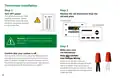
- Page 21: Troubleshooting & Frequently Asked Questions Can the BCC110 be used without Wi-Fi? The thermostat is functional without Wi-Fi after the initial setup has been completed. The Dual Fuel feature is disabled when Wi-Fi is unavailable. Will the BCC110 support all Wi-Fi systems & routers? This device only works with 2.4 GHz systems and is not compatible with 5.0 GHz systems. Trouble connecting to your home's Wi-Fi network? Make sure that your thermostat is a maximum of 20 ft or less from the router/modem without any obstructions. Power cycle your router/modem and then your thermostat before attempting to reconnect. If you still cannot connect, please contact the support team for further troubleshooting options. If the time does not update on the thermostat, you are not fully connected to the cloud server.
- Page 22: Wiring diagrams provide essential information for installation and troubleshooting. The BCC110 terminal and its key outline the connections for various components. Alarm input is designated for specific alerts. C-wire serves as the common connection. 1st stage heating and compressor are crucial for initial heating operations. The fan connection is necessary for airflow management. 2nd stage heating and compressor are used for additional heating capacity. Auxiliary connections support extra heating needs. The reversing valve is important for heat pump operations. Humidifier and dehumidifier connections help manage indoor air quality.
- Page 23: Wiring diagrams for single stage and two stage heat furnaces are provided. For single stage heat furnaces, ensure the system has a C-wire and the pre-installed jumper wire remains between RH and RC. Connect the R, C, W1, and G wires from the furnace to the corresponding terminals on the wall plate. For two stage heat furnaces, ensure the system has a C-wire and the pre-installed jumper wire remains between RH and R/RC. Connect the R, C, W1, W2, and G wires from the furnace to the corresponding terminals on the wall plate.
- Page 24: Wiring diagrams provide essential instructions for system connections. For single stage heat with a boiler, ensure the system has a C-wire. Keep the pre-installed jumper wire between RH and RC. Remove the jumper from the thermostat connection on the boiler and connect to RH and W/E. Bosch Greenstar boilers require an external transformer to power the thermostat. For combined single stage heat furnace and single stage cool air conditioner, ensure the system has a C-wire. Remove the pre-installed jumper wire from between RH and R/RC. Connect the furnace wires to the corresponding terminals on the wall plate. Connect the air conditioner wires to the corresponding terminals on the wall plate. Follow these steps for proper wiring and functionality.
- Page 25: Wiring diagrams provide essential information for heat pump systems. Heat pump systems are designed to provide heating and cooling using a single compressor, a reversing valve, and a fan. For a single stage heat pump, ensure the system has a C-wire. Ensure the pre-installed jumper wire remains between RH and R/RC. Connect the R, C, Y1, O/B, and G wires from the heat pump to the corresponding terminals on the wall plate. For a single stage heat pump with emergency heat and auxiliary heat, W/E controls emergency heat output, and W2/AUX controls auxiliary heat output. Connect the R, C, W1, Y1, O/B, and G wires from the heat pump to the corresponding terminals on the wall plate. Connect a jumper wire between W/E and W2/AUX.
- Page 26: Wiring diagrams for two stage heat pump with one stage emergency heat include ensuring the system has a C-wire. It is important to ensure the pre-installed jumper wire remains between RH and R/RC. Connect the R, C, W1, Y1, Y2, O/B and G wires from the heat pump to the corresponding terminals on the wall plate. For single stage cool air conditioner, ensure the system has a C-wire. Ensure the pre-installed jumper wire remains between RH and R/RC for the air conditioner. Connect the R, C, Y1 and G wires from the air conditioner to the corresponding terminals on the wall plate.
- Page 27: Wiring diagrams for combined single stage heat pump and single stage furnace (dual fuel) include essential connection instructions. Ensure the system has a C-wire and that the pre-installed jumper wire remains between RH and R/RC. Connect the R, C, W1, and G wires from the furnace to the corresponding terminals on the wall plate. Connect the C, Y1, G, and O/B wires from the heat pump to the appropriate terminals on the wall plate. A single humidifier or dehumidifier accessory can be controlled using the BCC110 thermostat. The thermostat supports humidifiers in heating operation and dehumidifiers in cooling operation, with only one accessory per thermostat. The wiring configuration for humidifiers and dehumidifiers is the same for all types of systems. The thermostat does not provide power to the accessory; it only provides control. Ensure that the accessory is externally powered and that the heat pump system is wired correctly. Connect the control wire of the accessory to the H/DH terminal of the wall plate.
- Page 28: Page 28
- Page 29: Main screen Main menu Fan Wi-Fi / cloud access Indicator Status System Mode Current room temperature Humidity set-points
- Page 30: Thermostat and app icons Basic icons System modes Fan modes Heat mode Cool mode Emergency heat mode Device settings System settings Heating types
- Page 31: System connectivity Unit operation Heat mode Schedule on device Schedule on cloud Cooling on (1st stage) & (2nd stage) Wi-Fi connection established Wi-Fi connection not established Internet is not available Emergency heating
- Page 32: Adjusting temperature setpoint(s) Schedule override on the app allows you to override the current schedule by scrolling the temperature up and down with your finger. Temporary adjustment will override the current set point in favor of the set point you enter until the next programmed time in the schedule. To permanently schedule the new set point, press the lock icon. Schedule override on the thermostat lets you override the current scheduled set point(s) by tapping the plus or minus (+/-) icons on the right side of the screen. In Auto mode, you can manually adjust either the Heat/Cool set points individually by selecting the appropriate bubble. Pressing the (+/-) icons will adjust both setpoints simultaneously if a Heat/Cool bubble is not selected.
- Page 33: Thermostat overview Unit operating mode Heat: The thermostat cycles your heating appliance to maintain your scheduled heating set point. Cool: The thermostat cycles your cooling appliance to maintain your scheduled cooling set point. Auto: The thermostat cycles your heating/cooling appliance to maintain your scheduled heating/cooling set points. Off: The thermostat turns off all heating/cooling functions. You can still manually operate the fan in this mode. Emergency heat (available only with heat pumps): The thermostat turns off all compressor stage(s) and activates the back-up electric heat source(s). Fan operation Auto: Fan will follow heating and cooling operations. On: Fan runs non-stop. Circulation: Fan cycles on and off regularly in addition to heating and cooling operations.
- Page 34: Thermostat overview You can enable automatic humidity control if the correct humidifier or dehumidifier accessory was correctly wired and configured during the thermostat’s initial setup. The thermostat turns on the humidifier during heating operation and the dehumidifier will be turned on during cooling operation. You can also configure the thermostat to operate similar to a humidistat. Alert: Send an alert message or turn on the system automatically when the room temperature is out of the range between set-points. Alerts are an additional source of protection for your heating/cooling appliance. You may only operate in either humidifier or dehumidifier mode and may not operate in both modes at the same time. The thermostat keeps track of your run time for the heating, cooling, air filter, and water pad. You can also set a reminder for air filter and water pad according to the number of calendar days. When it reaches its predefined run time, the thermostat displays a notification and sends a message to the registered smart device(s).
- Page 35: Additional information includes device information and weather forecast. Device information contains relevant account and system details. The weather forecast is based on the location of the installed thermostat. You must grant location access for the app to enable the weather feature. The system displays current hardware and software information and can be used to update firmware. There are three levels of screen brightness and three options for screen timeout. To reset the thermostat to its default factory settings, select advanced settings and choose factory reset. A 4-digit passcode is required to lock the screen. All settings will be lost during a factory reset, requiring a repeat of the initial setup process. Remember your screen lock passcode, as it is necessary to unlock the screen.
- Page 36: Page 36
- Page 37: Bosch EasyAir App The app allows you to remotely control all of your thermostat’s settings. You can adjust your schedule on-the-go or set it to vacation mode to save energy while you’re away. You can connect an unlimited number of thermostats and manage up to 4 schedules per thermostat. This is a perfect solution to help you achieve maximum comfort with minimum effort. In the App Store or Google Play, search “Bosch EasyAir App” and then download the app.
- Page 38: - App home tab - Notifications - Refresh / sync time - Thermostat screen lock - Actual room relative humidity - Actual room temperature - Heating setpoint - Cooling setpoint - Current schedule period - Cancel schedule override
- Page 39: Adjusting temperature setpoint(s) on the app involves tapping the current temperature. You can drag it left or right to change it or use the “+” and “-” buttons for adjustments. The setpoint change is temporary until the next scheduled period. For changing setpoints for scheduled periods, refer to the Schedule section in the manual. Click Hold to override the temperature setpoint permanently. Temporary and permanent overrides can be canceled at any time by clicking Cancel. In Auto mode, select either heat or cool before modifying the setpoint.
- Page 40: Schedule overview To add a new period to a given day, click the Add Period button in the middle of the screen. Individually select and set the starting time, heat setpoint, and cool setpoint. To modify an existing period, click on the 3 dotted menu button on the period you want to modify and select “Edit”. Click on the starting time, heat setpoint, or cool setpoint value you would like to edit and use the scroll wheel to update the value. To add a new schedule, use the Add Schedule button at the bottom, name your schedule, and click OK. To modify an existing schedule, click on the 3 dotted menu button on the schedule you want to modify and select “Edit” or “Delete”.
- Page 41: Schedule overview To delete an existing period, click on the 3 dotted menu button on the schedule you want to delete and select “Delete”. To copy a schedule to other days of the week, click on the “Copy Schedule” button. Then lettered days at the bottom of the screen until all days you would like to copy in the existing schedule have turned green and click Copy Schedule. Use the Finish button to save all changes.
- Page 42: App dashboard overview includes home, schedule, and settings. Users can view room temperature and adjust the set point. The buttons at the bottom of the BCC Home tab allow remote adjustments of system mode, fan mode, and accessory mode. Users can select a schedule or follow on-screen instructions to edit the default schedule or add new schedules. The settings tab is used to adjust temperature settings, date and time, location, screen lock, and view device information.
- Page 43: Page 43
- Page 44: Additional features Control your BCC110 with Amazon Alexa Bosch offers one Smart Home Skill for integrating your BCC110 with Alexa’s voice controls. You can control the BCC110 by saying: The Device Name is the name assigned to your device in the EasyAir app. You must have a registered EasyAir account to set up and use your thermostat with Amazon Alexa.
- Page 45: Connecting your BCC110 to Amazon Alexa Download the Bosch EasyAir, create a SingleKey ID account, and add your BCC110 thermostat to the App. Download the Amazon Alexa app and set up your Alexa-enabled device. In the Amazon Alexa app, click on the Menu button in the top left corner. Click on the Skills section and search for “Bosch EasyAir” in the search bar at the top of the page. After you find and click on the Bosch EasyAir Skill, click on the blue Enable button. The setup process redirects you to the SingleKey ID sign in page where you will need to enter your SingleKey ID username and password. After you have received confirmation that your two accounts have been successfully linked, click Done in the top left hand corner. Next click Discover Devices in the Amazon Alexa app or say “Alexa, discover new devices.” Device Discovery could take up to 45 seconds. When device discovery is complete, you should see a list of connected devices in the Smart Home menu of your Amazon Alexa app. The setup process is now complete and you can start to control your BCC110 with your Alexa-enabled device.
- Page 46: Connecting your BCC110 to Google Assistant Download the Bosch EasyAir app, create a SingleKey ID account, and add your BCC110 thermostat to the app. You must have a registered BCC account to set up and use your thermostat with Google Assistant. Download the Google Home app and set up your Google-enabled device. In the Google Home app, click on the add button in the middle of the screen. Click on Setup device and select the link option under Works with Google. Search for Bosch EasyAir and click add new Bosch EasyAir. The setup process redirects you to the SingleKey ID sign in page where you will need to enter your SingleKey ID account username and password. Next choose the device(s) you want to link to your Google Home from the available list and click Next. Choose a home for your new thermostat and click Next. The setup process should now be complete and you can start to control your BCC110 thermostat with your Google-enabled device.

EUROTRONIC COMET Programmable Energy Saving Radiator Thermostat User Manual

Moes WHT-PJ01 Smart WiFi Thermostat User Manual

RTH21 Programmable Thermostat Coldbuster Dual Instruction Manual

thermotouch 5235W Wi-Fi Programmable Thermostat Instructions

EPH CDTP2 Room Thermostat Installation Guide

Sygonix 2735095 Wireless Indoor Thermostat Instruction Manual

marmony MTC-40 Radio Controlled Room Thermostat Instruction Manual

EPH CONTROLS CDT2 Room Thermostat Instruction Manual

finder 7T Series Enclosure Thermostat User Guide

AVATTO WT598 1T1 Smart Thermostat