
Home > HASWILL ELECTRONICS > Haswill Electronics STC-9200 Thermostat User Guide
Haswill Electronics STC-9200 Thermostat User Guide


4.2. Indicator / Character in Display
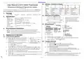
User Manual of STC-9200 Thermostat
Refrigeration & Defrosting & Evaporator Fan Controller
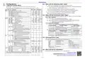
Indicator
(Version 22.11.07GEN)
Meaning
On
Compressor status
Working
Setting Status
Setting
Normal
N/A
Fan Status
Working
Stop
Defrosting status
Working
The STC-9200 temperature controller controls the power supply status of the connected Refrigeration
device, the defrosting unit, and the Evaporator Fan, typically suited to an oversized freezer room.
Hide
Stop
Stop
Wink
Time Delay
Time Delay
N/A
Dripping Water
1. Package
Fast Wink
N/A
Manually Refrigeration
Manually Defrosting
Controller: 1PCS
Sensor: 2PCS
Clips: 2PCS
Manual:1 PCS Waterproof Cover: 1PCS
4.3. Dimensions & Installation
2. Specification
Input Power
1) Mount size: 71*29*85 mm (W*H*D);
2) Detach the slide fasteners, put the
controller into the hole, and wire it.
3) Install the fasteners and the waterproof
cover.
220V AC ± 10% 50/60HZ; (12/24/48/110V Option)
8A (Default) under 250V AC
Maximum current
Thermistor / Sensor
Protection Class
Storage
NTC, 25°C /10 KΩ, the sensor cable 200cm
IP65 to the front panel
-10°C ~ 60°C, RH<90%, without condensation
Measurable: -50.0°C ~ +50.0°C; Controllable: -50.0°C ~ +50.0°C
0.1°C
Temperature Range
Resolution
4.4. Wiring Diagram
Accuracy
± 1°C from -40°C to +50°C; ± 2°C in other range
≤ 3W
Power Consumption
3. Environmental Information
The package's material is 100% recyclable. Just dispose of it through specialized recyclers.
The electro components can be recycled if it is disassembled for specialized companies.
Please do not burn or throw the controllers in domestic garbage. Observe the respective law in your
region concerning the environmentally responsible manner of disposing of its devices.
4. Appearance & Operation
4.1. Front Panel & Operation
A. 10K NTC sensor, need not distinguish + or -.
B. The input voltage must be within the voltage value marked in the diagram ±10% value.
Under normal status, the screen shows room sensor temp.
C. Suggest Load Power ≤ Voltage∗ Max current of Relay
A. Hold the
for 3s to enter/exit the user setting
Factor
interface to check and modify the set-point and the
hysteresis here.
B. Hold the
4.5. Copykey (Optional)
key and the
key at the same time
A. Upload to Controller
for 10s to lock/unlock the admin menu:
OFF = unlock, editable
ON = locked, only can check the value, not editable.
1)
2)
3)
Insert the Copykey, Press the
Now Press the key to upload data will show "END" once finished;
Shut down the controller and then pull out the Copykey.
key, the display shows "UPL";
B. Download from Controller
C. Hold the
and the
keys for 10s to enter admin interface; Press the
or key to change the data; Press the
to check
again to save
1)
Assure controller being shut down and insert the Copykey, then starting up
current data, and press the
data and back to menu list; If without operated in 10s, the new data will be auto-saved.
D. Hold the
E. Hold the
it again to quit.
F. Hold the
2)
The controller will scan the Copykey and download data automatically, shows "DOL"
when downloading, and shows "END" once finished.
for 3s to check the defrost sensor temp.;
for 3s to trigger the forced refrigeration mode manually (conditions in 5.3); do
3)
Attention:
Restart the controller; it will work according to the new data.
⚫
Part of the parameters will be executed in the next cycle; please power off the controller and
power back to start a new cycle for running by the new data without a wait.
for 3s to trigger the forced defrosting mode manually (conditions in 5.2); do it
⚫
If a parameter in the Copykey exists error or in the wrong format, the display shows ERR.
again to enter defrosting water dripping status.
1 / 2


| General | Details |
|---|---|
| Name | Haswill Electronics STC-9200 Thermostat User Guide |
| Make | HASWILL ELECTRONICS |
| Language | English |
| Filetype | PDF (Download) |
| File size | 0.24 MB |
 (1 votes, average: 5.00 out of 5)
 Loading...

Haswill Electronics STC-9100 Thermostat User Manual

Haswill Electronics RC-113M PID Thermostat User Guide

Haswill Electronics STC-8080A+ Thermostat User Guide

Haswill Electronics AL8010H Thermostat User Guide

HASWILL ELECTRONICS STC-200 Thermostat User Guide

Haswill Electronics STC-8080H Thermostat User Guide

Haswill STC-9200 Manual: Questions and Answers
Haswill STC-9200 specifications
| Maximum load | 8A (Default) under 250V AC |
| Accuracy | ± 1°C from -40°C to +50°C; ± 2°C in other range |
| Storage temperature | -10°C ~ 60°C, RH<90%, without condensation |
| IP rating | IP65 to the front panel |
| Power consumption | 3W |
What does the 'Wink' indicator mean on a Haswill STC-9200 display?
Wink shows time delay for the compressor, normal setting status, and time delay dripping water for defrosting. User Guide, p. 1
What's the difference between 'On' and 'Hide' status on the Haswill STC-9200?
On means the compressor is working and the fan is working. Hide means the compressor and fan have stopped.
| Status | Compressor |
|---|---|
| On | Working |
| Hide | Stop |
What do the display symbols mean on STC-9200 thermostat?
On, Hide, Wink, and Fast Wink indicate compressor and fan activity, with Wink showing time delay states. User Guide, p. 1
More Haswill thermostat manuals

Beca BHT-9000 Smart Knob Thermostat User Guide

Beca BHT-9000 Thermostat User Guide

VENSTAR Fan Coil Thermostat T2100 / T2150 User Guide

Honeywell evohome Smart Thermostat User Guide

Infracomfort HY312W Wifi Digital Thermostat User Manual

GENERAL SENNA 270 Smart Room Thermostat User Manual

network thermostat X-Series Ethernet Thermostat Instruction Manual

OUELLET OTL221 Single Pole Mechanical Thermostat Instructions

BEOK TCB38WIFI Color TFT-LCD Heating Thermostat User Manual

GENERAL LIFE Senna 330S RF Wireless Room Thermostat User Manual